Facebook
 Google
 GitHub
 Linkedin
Parallel Operation: Influence of Power Module Parameters
The challenge of IGBT module paralleling is to understand the necessary de-rating of power converters under consideration of different module parameters. This understanding is important for proper module parallel operation inside the thermal and safe operation limits. This article describes the methodology of how to analyze the influence of module parameters on current sharing and switching energy imbalance for parallel operation of power modules.
The current imbalance during module operation can be caused both by the characteristics of the parallel power modules, such as the different forward voltage, and the design of the power converter itself. The interface of power modules, such as the power connection on the DC and AC side, the design of the gate driver, and the gate driver connection to the power modules, have an influence on the static and dynamic current imbalance of modules connected in parallel.
An overview of the various factors that influence the performance of the power modules connected in parallel is shown in Figure 1.
In the figures below, the focus is on the analysis of the IGBT and diode characteristics with regard to current imbalance in parallel-connected power modules. For the following analysis, uniform cooling conditions are considered.
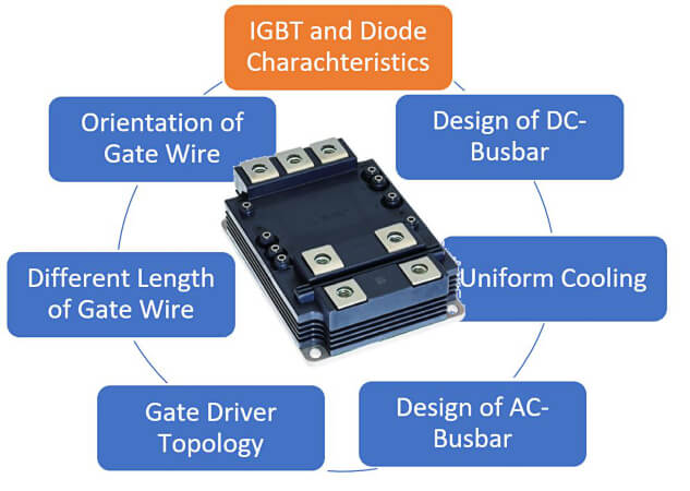
Figure 1. Factors affecting the performance of power modules connected in parallel. Image used courtesy of Bodo’s Power Systems [PDF]
Evaluation Setup and Test Sample
Each rolling stock manufacturer has its own unique converter design, so it would be difficult for semiconductor manufacturers to make representative power module analyses without a standardized test setup. This difficulty was discussed in Horizon 2020 Project “Shift2Rail” [2]. The project members agreed to define a standardized interface between the semiconductor suppliers and power converter manufacturers to discuss de-rating for power modules. The reference setup is shown in Figure 2. One of the goals of reference setup is to reduce the influence of external components on the current imbalance of parallel connected power modules as much as possible. On the DC side, each power module has an individual DC-link capacitor; the AC power connection is made via a wide busbar with a central load connection under the modules. Only one central gate driver is used in combination with a low-inductive interface board to control the paralleled modules.
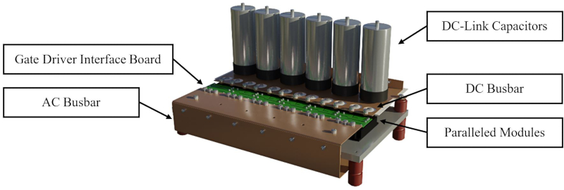
Figure 2. Reference test setup for paralleling evaluation. This article originally appeared in Bodo’s Power Systems [PDF] magazine.
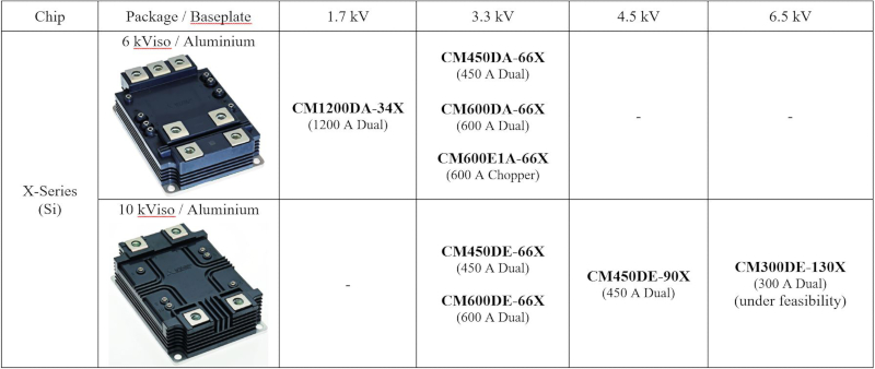
The reference test setup was chosen for the investigation of module parallel connection. CM450DA-66X module in the LV100 package is a representative X-Series power module that was selected as a device under test for performing the evaluation and analysis. The X-Series line-up with silicon chipset and aluminum base plate is shown in Table 1. These power modules feature the latest X-Series 7th Gen. cutting-edge chipset with CSTBT(III) trench IGBT and RFC diode. Both IGBT and diode chips have a positive temperature coefficient for forward voltage over a wide current range. This feature is beneficial for thermal balancing between the parallel connected modules during operation if the temperature is not evenly distributed across the heatsink. The NTC temperature sensor, which is integrated into the module, allows the monitoring of case temperature for each individual parallel connected module. In addition, the dual-power modules of the Xseries use a new innovative aluminum base plate with integrated AlN ceramic insulation, the so-called MCB (Metal Casting direct Bonding) baseplate. The new baseplate structure has a significantly smaller junction-to-case thermal resistance compared to the conventional structure, which allows output-power increase or reduction of the operating junction temperature. In addition, Mitsubishi Electric’s X-Series power modules offer features for demanding railway applications, such as high CTI value of housing material, partial discharge measurement, high-quality control, and traceability.
Table 1. LV/HV100 X-Series line-up. Image used courtesy of Bodo’s Power Systems [PDF]
Correlation of Power-Module Parameters and Parallel-Switching Waveforms
To investigate the impact of different IGBT power module parameters on the current sharing, parallel connections of ten different pairs of power modules have been measured. Afterward, linear regression analysis is performed to correlate characteristics of switching waveforms and power-module parameters.
The devices under test are 3.3 kV/450 A (CM450DA-66X) power modules in the LV100 package. These devices show a natural distribution in their electrical parameters. Hence, collector-emitter saturation voltage ranges from 2.61 V to 2.81 V, gate-emitter threshold voltage ranges from 6.56 V to 7.70 V, and diode forward voltage ranges from 2.20 V to 2.45 V. The ten pairs have been analyzed regarding their switching characteristics during turn-on, turn-off, and reverse recovery.
Turn-off Switching Analysis
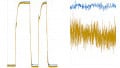
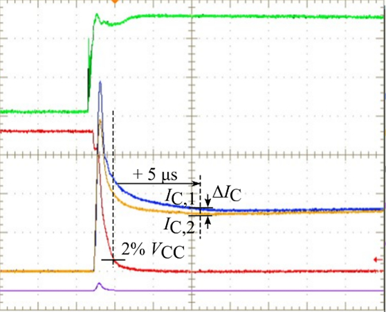
Figure 3 shows two exemplary turn-off measurement results. When IGBT device parameters are similar, nice current sharing can be achieved. On the contrary, in the case of different power module parameters, the load current is unequally shared between power modules.
With linear regression analysis of the ten pairs, the correlation between IGBT power module parameters and switching characteristics is determined. It is found that the difference in steady-state current ΔIC correlates with the difference in collector-emitter voltage only. Other power module parameters are found to be insignificant (determination coefficient < 95%). Linear regression analysis leads to the following relationship for the current imbalance. Please refer to [3] for further details.
\[\frac{\Delta I_{C}}{IC_{avg}}\approx-0.56V^{-1}\cdot\Delta V_{CEsat}\] (1)
Turn-on Switching Analysis
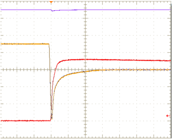
Figure 4 shows turn-on switching waveforms with two power modules connected in parallel. If power module parameters are similar, the current will share equally between both power modules. However, when power modules are different, unequal current sharing between power modules is to be expected.
It is found that current sharing correlates with gate-emitter threshold voltage difference ΔVGE(th) and difference in forward voltage of the complementary free-wheel diodes ΔVEC. Linear regression analysis leads to the following relationship for the current imbalance.
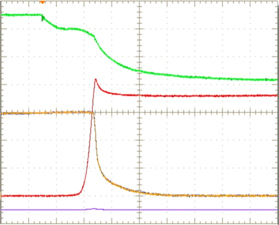
(a) similar device parameters
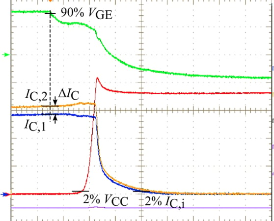
(b) different device parameters
Figure 3. Exemplary turn-off waveforms (green: VGE 10V/div, blue: IC1 150A/div, yellow: IC2 150A/div, red: VCE 500V/div, 2.0 us/div). Image used courtesy of Bodo’s Power Systems [PDF]
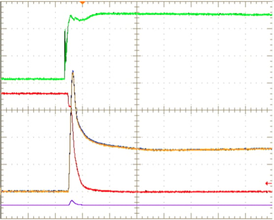
(a) similar device parameters
(b) different device parameters
Figure 4. Exemplary turn-on waveforms (green: VGE 10V/div, blue: IC1 300A/div, yellow: IC2 300A/div, red: VCE 500V/div, 2.0 us/div). Image used courtesy of Bodo’s Power Systems [PDF]
(a) similar device parameters
(b) different device parameters
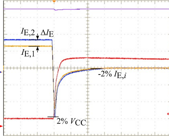
Figure 5. Exemplary reverse-recovery waveforms (blue: IC1 300A/div, yellow: IC2 300A/div, red: VCE 500V/div, 2.0 us/div). Image used courtesy of Bodo’s Power Systems [PDF]
\[\frac{\Delta I_{C}}{IC_{avg}}\approx-0.18V^{-1}\cdot\Delta V_{EC}-0.18V^{-1}\cdot\Delta V_{GE(th)}\] (2)
Diode Reverse-recovery Switching
Exemplary switching results of diode reverse recovery are shown in Figure 5. Again, the current shares equally between two power modules if the power-module parameters are similar. If the power module parameters are different, differences in the static current and in the peak reverse recovery current become visible.
Linear regression analysis shows that the static current sharing correlates solely with the difference of diode forward voltages ΔVEC. Other power-module parameters are found to be insignificant. The following relationship for the current imbalance is found.
\[\frac{\Delta I_{E}}{IE_{avg}}\approx-0.78V^{-1}\cdot\Delta_{EC}\] (3)
De-rating Calculation up to Six Times Paralleling
Based on derating factors for currents and energies, the required derating in the case of parallel connection of more than two modules can be defined. For this, it will be assumed that one of the paralleled modules has a minimum characteristic (resulting in maximum switching energy or current) while all other modules have the maximum characteristics (leading to minimum switching energy or current). By using the following equation, the derating ratio for the collector current for more than two parallel connected modules can be calculated as an example.
The parameter n is the number of parallel connected modules. The parameter x is the identified imbalance ratio from the measurement of two parallel connected modules (for example (∆IC/ICavg according to (1) and (2) or (∆IE/IEavg according to (3)). As a result, the de-rating dependency on the grouping parameter can be defined, as shown in Figure 6. The figure already illustrates that confidence intervals, as determined by the regression analysis, become also very helpful regarding the derating ratio of multiple power modules.
\[\frac{I_{C,max}}{I_{C,avg}} - 1 = \frac{I_{C,max}}{\left( (\eta -1) I_{C,min} + I_{C,max}\right)/\eta} - 1 \frac{\eta \cdot I_{C,max}}{\left( (\eta -1)\left( \frac{1-x}{1+x} \right) I_{C,max} + I_{C,max}\right)} - 1\frac{\eta}{\left( (\eta -1)\left( \frac{1-x}{1+x} \right) + 1 \right)} - 1\]
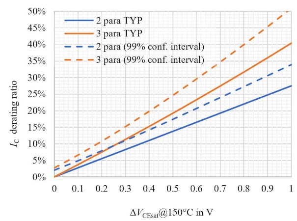
Figure 6. Collector current derating ratio versus forward voltage difference. Image used courtesy of Bodo’s Power Systems [PDF]
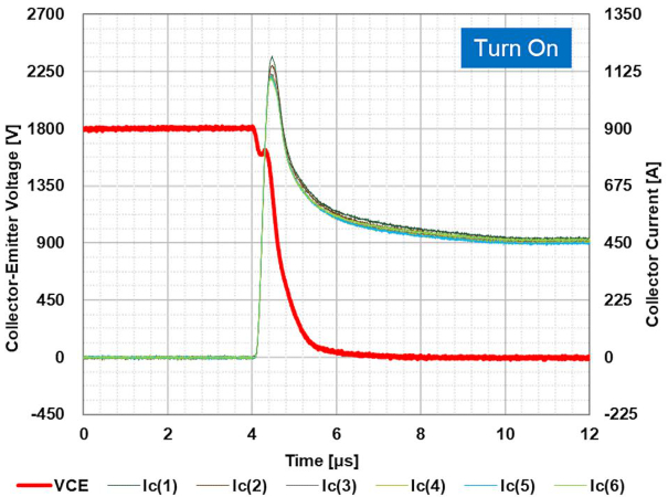
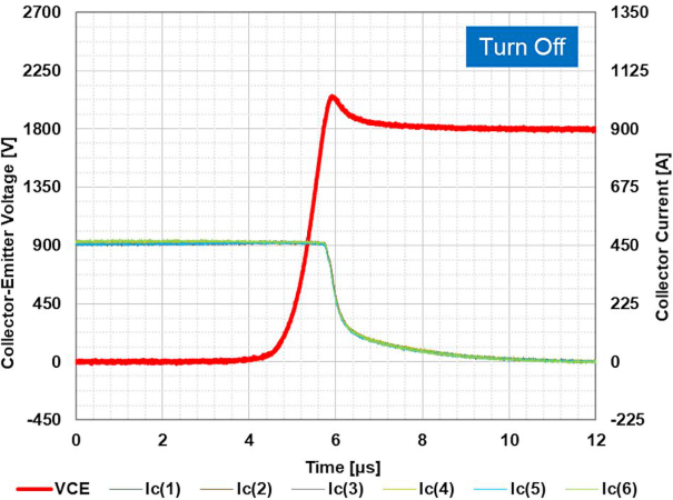
Figure 7. Switching waveforms for 6-times parallel connection (conditions: Vcc = 1800V, Ic = 2700A (450A per device), Tj = 150°C, VGE = +15V / -9V, RG(on) = 2.7Ω, RG(off) = 62Ω, CGE = 33nF). Image used courtesy of Bodo’s Power Systems [PDF]
Conclusion
This article explains a methodology to investigate the influence of power-module parameters on the switching characteristics of a parallel connection. For each switching type, IGBT turn-off, turn-on, and diode reverse recovery, the influence of the different device parameters is investigated. Considering only the significant parameters, a model is provided to calculate differences in switching characteristics on arbitrary device parameters. It is shown how the results are transferred to a parallel connection with more than two devices. Finally, homogeneous current sharing between six devices in a parallel connection is confirmed. The switching waveforms prove that with a well-designed converter layout and well-paired LV100 modules, ideal current sharing is achieved.
References
[1] T. Wiik, D1.2, New generation power semiconductor, Common specification for traction and market analysis, technology roadmap, and value cost prediction, Roll2Rail, H2020 - 636032, 2016.
[2] A. Nagel, J. Weigel, et. al., Paralleling reference setup, Shift2Rail, Pinta, H2020 - 730668, 2019.
[3] Y. Ando, J. Sakai, K. Hatori, N. Soltau and E. Wiesner, “Influence of IGBT and Diode Parameters on the Current Sharing and Switching-Waveform Characteristics of Parallel-Connected Power Modules,” 2022 24th European Conference on Power Electronics and Applications (EPE’22 ECCE Europe), 2022, pp. 1-11.
Featured image used courtesy of Adobe Stock
This article originally appeared in Bodo’s Power Systems [PDF] magazine.
Related Content