Facebook
 Google
 GitHub
 Linkedin
Optimizing the Frequency Properties of Silicon IGBTs
This article proposes a method to obtain optimal properties of silicon fast IGBT chips designed for joint operation with SiC SBD in hybrid modules. The optimal doses of proton irradiation, as well as optimal static and dynamic properties of 1200V IGBT, are determined for hybrid modules used in DC/DC converters at operating frequency of up to 50 kHz.
One of the most promising directions in the evolution of high-spec auxiliary power sources in terms of power semiconductors is related to the use of "hybrid" semiconductor switches based on silicon IGBTs and SiC Schottky diodes. The use of Schottky diodes makes it possible to drastically reduce the frequency-dependent component of the power loss in the diode, to reduce the turn-on energy losses in the IGBT, and to expand the safe operation area of the switch elements in modes typical for power electronics. Using a silicon IGBT allows to optimize the cost of the device.
This requirement to reduce the frequency-dependent component of the loss power highlights the need to improve the frequency properties of the IGBT, since it is this element that limits the frequency response of the entire hybrid switch.
Various aspects of optimizing silicon IGBTs using proton irradiation technology to improve their frequency response are discussed below.
Experimental Samples
The experiment was based on samples of Trench Field Stop IGBT chips rated for blocking voltage up to 1200 V and nominal current up to 200 A having a thickness of 125 μm.
The frequency properties of the IGBT were improved by means of proton irradiation, the related technology was described in detail in [1]. The dose of proton irradiation varied, making it possible to obtain chips with various combinations of static and dynamic properties. The path length of hydrogen atoms remained the same.
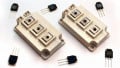
The experimental IGBTs were designed to operate together with SiC Schottky diodes in hybrid (Si / SiC) modules.
Experimental modules were tested for the following properties:
- IGBT collector-emitter saturation voltage (Vc sat) at the temperature of 25 and 150°C, collector current Ic = 0.25 x Inom and Ic = I nom, and the voltage across the gate 15 V;
- energy of IGBT turn-on losses Eon, energy of IGBT turn-off losses Eoff. Measurement conditions: temperature 25 and 150°C; collector-emitter voltage 600V; gate-emitter voltage ± 15V; resistance in the gate circuit 2.2 Ohm; stray inductance in the DC circuit of the tester unit below 35 nH; collector current from 0.4 x Inom to 1.5 x Inom. Stray inductance of the module structure made around 20 nH.
Dosage Relations of Vce, Eon, Eoff
Typical relations between Vce sat, Eon, Eoff of the IGBT and the dose (integral flux - Ф) of protons are shown on Figures 1, 2.
The Vce sat relation can be reliably approximated by a linear function:

In similar fashion to (1) it is possible to approximate the dosage relations between the current and components of piecewise-linear approximation of the Vce sat relation: cut-off voltage (VT0) and dynamic resistance rT:
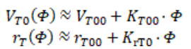
Figure 2 demonstrates that the dosage relation for Eon is almost absent for SiC SBD modules, and the Eon value measured in “nominal” mode described above (Eonnom) is rather low.
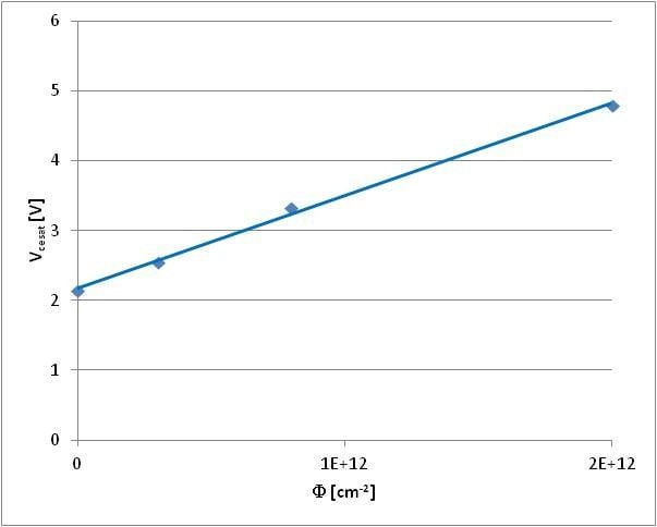
Figure 1: Typical relation between Vcesat and dosage. Ic=Inom=200 A, Tj=150 C
Analysis of the relation between Eoff and dosage shows that it can be approximated with a relation:
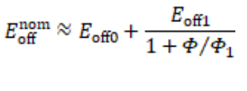
where Eoffnom is Eon value measured in “nominal mode” described above, Eoff0 – component of loss energy that does not depend on irradiation treatment
E0ff1 – component of loss energy that depends on irradiation treatment, ф1 – constant.
Relations between Eon / Eoff and current/voltage are roughly directly proportional:
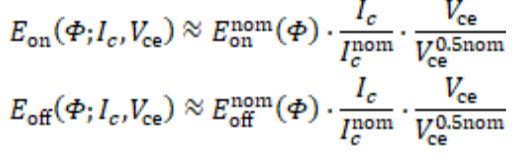
where Ic nom = 200 A is the nominal collector current, Vc 0.5nom = 600 V is the collector-emitter voltage measured in nominal mode.
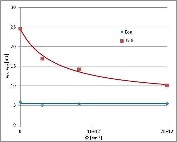
Figure 2: Typical relation between Eon / Eoff and dosage. Ic=Iсnom=200 A, Tj=150 C
Approach to Optimization
The loss of power at the IGBT (Ploss) consists of "static" and "dynamic" components. "Static" one is mainly caused by the flow of collector current through a turned-on device and depends on the current and voltage of the collector-emitter saturation (Vcesat), but is not affected by the frequency. "Dynamic" component is caused by the dissipation of energy in transient processes of turning-on and turning-off and is directly proportional to frequency (f).
The technology to improve the frequency properties (in this case, proton irradiation) makes it possible to reduce the dynamic component of the loss power. However, it achieves it at the cost of increasing the static component, and while the former decreases monotonically, the latter increases monotonically along with increasing the radiation dose [1, 2].
Thus, we can obtain a family of dependencies between loss power and frequency at various radiation doses for any specific operating mode of the switch, similar to that shown in Figure 3. The envelope of this family, shown in Figure 3 with the red line, is in fact the limit line showing the lowest loss power for a switch of the given design and technological version operating in a particular mode. Each point of this limit line corresponds to a certain optimal dose of proton irradiation allowing to obtain the minimum loss power when operating the switch at a given frequency. This optimal radiation dosage can be determined from the condition of a local minimum of energy losses:
dPloss(F; f, Ic, Vce)/dF=0
Knowing the relation between the dosage of proton irradiation and such IGBT properties as Vce (VT0, rT), Eon, Eoff, it is trivial to construct a specific limit line and determine the minimal loss power of a switch at specific frequency, the required proton irradiation dosage and optimal values of Vce, Eon, Eoff for that dosage.

Figure 3: Optimal loss power
Finding the Optimal Properties of Hybrid Switch Operating in an Auxiliary Power Source
Let us find the optimal properties of IGВТ for a hybrid chopper switch used in a step-down DC/DC converter with the following properties: DC input voltage 560 V, DC output voltage 300 V, output current up to 100 A. Using the relation (5) and taking into account (2), (3), (4) it is easy to obtain a formula linking the value of optimal irradiation dosage (фopt) to frequency and values of the collector current and voltage:
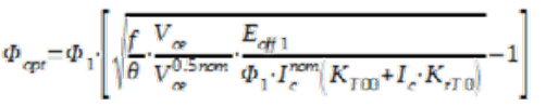
where Ѳ = 0.54 is the current fill factor for an IGBT used in the converter described above.
Figure 4 shows relations between фopt and frequency for various I c/Ic nom.

Figure 4: Relation between фopt and frequency.
Figure 5 shows the limit line of minimal loss power at an IGBT obtained using relation Fopt at Ic/Ic nom = 0.5. It shows that this line in the frequency range up to 50 kHz can be reliably approximated with relations between frequency and loss power of two module series – fast and ultrafast. Their IGBT irradiation dosages are marked with dots on Figure 4. The Figure shows that using the FAST series is optimal for frequencies up to 12 kHz and ULTRAFAST series for frequencies above 12 kHz. In both cases the maximum operating frequency of a device is limited by the maximal power of heat removed by a heatsink and resulting temperature of the module baseplate (liquid cooling was selected for this example).

Figure 5: Limit line of a minimal loss power at an IGBT and its approximations by relations between frequency and IGBT loss power for two module series – fast and ultrafast.
If we accept 100A as the nominal current of the above-mentioned hybrid modules, the typical IGBT properties at 150 °C will be as follows:
- for the fast series – Vcesat = 1.62 V, Eon = 2.75 mJ, Eoff = 10.0 mJ;
- for the ultrafast series – Vcesat = 2.5 V, Eon = 2.75 mJ, Eoff = 6.0 mJ.
We proposed a method to determine the optimal properties of fast silicon IGBT chips intended for joint operation with SiC SBD in hybrid modules. The optimal doses of proton irradiation, as well as optimal static and dynamic properties of 1200V IGBT, are determined for hybrid modules used in DC/DC converters with an operating frequency of up to 50 kHz. It should be noted that using IGBTs of a different design and with a different technology of increasing the speed, as well as changing the topology and operating mode of the converter will, of course, lead to a change in numerical values of the parameters and constants used in this method. However, it can be expected that the structure of the proposed formulas will not change.
References:
[1] T. Fujihira, M. Otsuki, O. Ikawa, A. Nishiura, N. Fujishima, “The State-of-The-Art and Future Trend of Power Semiconductor Devices”, Proc. PCIM Europe 2015, Nurnberg, 2015, pp. 27-35.
[2] A. Nakajima, S. Nishizawa, H. Ohashi, W. Saito, “Theoretical Loss Analysis of Power Converters with 1200 V Class Si-IGBT and SiCMOSFET”, Proc. PCIM Europe 2015, Nurnberg, 2015, pp. 951- 957.
[3] A. M. Surma, V. V. Verevkin, K. A. Volobuev, “Optimizing Properties of Fast IGBT and FRD with Partially Diffused Proton Beam Irradiation”, Proc. EPE ECCE 2019, Genova, 2019.
[4] A. Surma, K. Volobuev, T. Kulevoy and V. Stolbunov, “Using Proton Irradiation with Initial Energy over 10 MeV to Improve Turn-off Time of High Power IGBT and FWD”, Proc. ICEPDS 2018, Novocherkassk, 2018.
This article was co-authored by Alexey Surma, Dmitry Titushkin, Denis Malyy, Vladimir Verevkin, and Kirill Volobuev. This article originally appeared in Bodo's Power Systems Magazine.
Related Content