Facebook
 Google
 GitHub
 Linkedin
DC-Link Management for Regenerative Servo Drives
Learn about DC-Link management for regenerative servo drives—brake choppers, sizing, and EMI pitfalls.
This article is published by EEPower as part of an exclusive digital content partnership with Bodo’s Power Systems.
DC-link management is the discipline that keeps energy on the DC bus of a regenerative servo drive safe, stable, and useful. Braking events can push bus voltage up in milliseconds, and poor design can turn that energy into trips, heat, or electromagnetic noise instead of productivity. The hook is simple. Every deceleration either pays you back or punishes you.
The importance is high because modern machines pack more inertia and faster cycles into smaller cabinets where margins are thin. In this guide, you will learn what the DC link is, why regeneration stresses it, how brake choppers actually behave, how to size choppers and resistors correctly, and how to avoid the most common EMI pitfalls. You will also see when an active front end is the smarter option and when a humble resistor is all you need.

Image used courtesy of Adobe Stock
We will keep the tone practical so you can apply the ideas the same day on a real machine. By the end, you will have a concise playbook for safer decels, quieter cabinets, and fewer nuisance faults.
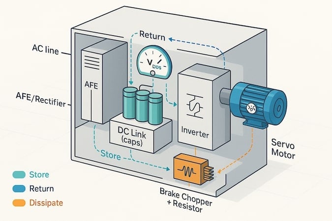
Figure 1. How servo drives manage energy flow: storing, returning, or dissipating regenerated power inside a motion-control system. Image used courtesy of Bodo’s Power Systems [PDF]
What is the DC link in a servo drive?
The DC link is the intermediate energy store that connects the rectifier or active front end to the inverter stage that feeds the motor. The DC link smooths pulsating input power, provides a local reservoir of energy, and sets the reference voltage that the inverter switches against. A stable DC link reduces current ripple, improves control loop headroom, and limits overvoltage trips during braking. The block view is simple. AC line flows to a rectifier or AFE, then to bus capacitors and film decoupling, then to an inverter that produces three-phase PWM to the motor. During motoring, the DC link delivers energy to the motor. During regeneration, the motor returns energy that raises the bus voltage.
Typical servo buses run from roughly 300 to 800 VDC, depending on mains and topology. Capacitance spans hundreds to thousands of microfarads, and ripple targets sit in the low single-digit percent under-rated load before regen events occur. For background on motion power stages and DC bus behavior, a useful primer on modern servo drives helps connect control concepts to practical hardware decisions.
1. Typical bus voltages: 325 VDC for 230 VAC class, 565 VDC for 400 to 480 VAC class, higher for specialty systems
2. Typical capacitance: 470 µF to several mF, depending on power and sharing
3. Typical ripple targets: 2 to 5 percent under steady load, briefly higher during transients
DC bus capacitors
DC bus capacitors are energy storage components that reduce ripple and absorb short transients on the DC link within a servo drive. In this context, the capacitors define how stiff the bus feels to sudden load changes and how much short-term regen energy can be buffered before other actions are needed. Electrolytic capacitors offer high capacitance density with higher ESR and limited lifetime. Film capacitors offer low ESR and excellent high-frequency performance with lower capacitance per volume. Thermal performance, ripple current rating, and lifetime at hot-spot temperature dominate selection. Higher ESR increases losses and temperature rise, which shortens life. Lower ESL and strategic placement near switching nodes tame ringing and radiated noise.
1. Selection factors: voltage margin of at least 20 percent, ripple current rating at worst-case temperature, ESR and ESL at PWM frequencies, lifetime at hot-spot per manufacturer curves, mounting and creepage for the cabinet environment.
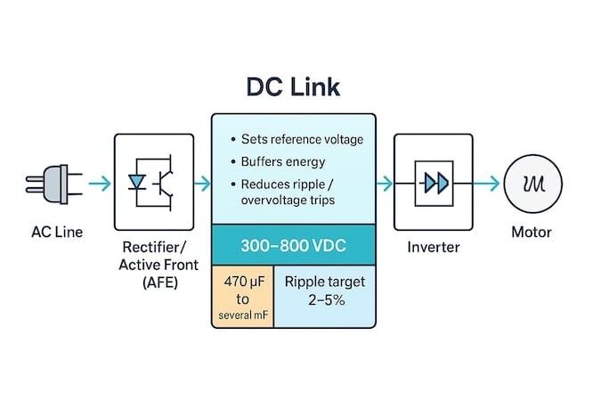
Figure 2. The DC link acts as the energy buffer and voltage stabilizer between the rectifier and inverter, ensuring smooth, reliable power delivery to the motor. Image used courtesy of Bodo’s Power Systems [PDF]
Precharge circuit
Precharge is the process that limits inrush current to DC bus capacitors when a servo system powers up, so components are not stressed and breakers do not trip. In this article, the precharge matters because big capacitor banks look like a short at t0. A resistor, NTC, or active precharge path fills the capacitors gradually before the main contactor closes. The main applications include multi-axis buses, drives with large electrolytic banks, and systems with lineside contactors. The working principle is straightforward. Insert a resistance or a controlled switch to limit current, sense the bus voltage to a threshold, then bypass with a contactor.
1. Common topologies: fixed resistor and contactor bypass for simplicity, NTC thermistor for cost-sensitive builds, active MOSFET precharge for tight control and reduced heat, sequence options for multi-supply cabinets
Why do regenerative servo drives need DC-link management?
Regenerative servo drives need DC-link management because braking events push energy back into the DC bus, which raises the bus voltage toward overvoltage trip limits. The subject is not optional. Unmanaged regeneration stresses capacitors, triggers faults, and can compromise safety. The general picture is that energy that was kinetic becomes electrical and has to go somewhere quickly. The details include how motion profiles concentrate energy, how vertical axes inject constant regen when lowering, and how multiple axes couple through a shared bus. The outcome is predictable. Either you return it to the grid, buffer it briefly, or burn it as heat in a resistor. Good management keeps the DC link inside safe limits while maintaining machine throughput.
1. Fast bus rise scenarios: high inertia rapid decel, emergency stops from top speed, gravity loads on Z axes, multiple axes braking at once on a shared supply.
Where does the energy go during braking?
Braking energy goes to one of three places by design. The drive can push it back to the grid through an active front end, the capacitors can store it for a short interval, or a brake chopper can dump it as heat in a resistor. Returning to the grid is most efficient but requires cost and commissioning. Storing in capacitors is temporary and sized by ripple and trip limits. Dumping to a resistor is simple and robust for short bursts.
1. Returned to grid: highest efficiency and improved power factor, best for sustained regen and energy savings, requires AFE hardware and setup.
2. Stored in DC caps: zero wiring complexity and instant response, limited by voltage rise and ripple current, best for small or very brief events.
3. Dissipated in a resistor: low cost and simple logic, thermal design required, best for intermittent or bursty regen profiles.
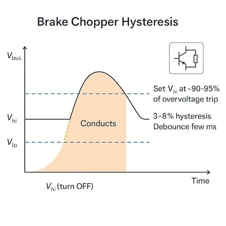
Figure 3. Brake chopper hysteresis controls when excess DC-bus energy is dissipated, preventing overvoltage trips during regeneration. Image used courtesy of Bodo’s Power Systems [PDF]
How does a brake chopper work?
A brake chopper is a protection and energy management technology that senses DC bus voltage and switches a transistor to divert current into a braking resistor when the bus exceeds a set threshold. In this context, a chopper turns dangerous peaks into controlled heat so the drive continues operating. The main applications are machines with intermittent deceleration energy, gravity axes that need a sink, and shared buses that see combined braking. The working principle is threshold control with hysteresis. When Vbus rises above V_hi the chopper turns on and current flows into the resistor. When Vbus drops below V_lo the chopper turns off. Device choice can be IGBT or MOSFET, depending on bus voltage and current. Thermal limits, duty cycle, and coordination with drive overvoltage settings define safe operation.
1. Key parameters: V_hi and V_lo thresholds, peak current, switching duty, average power, resistor value and rating, thermal class, and cooling approach
What operating thresholds and hysteresis should you set?
The operating thresholds should be set below the drive’s overvoltage trip and above normal ripple so the chopper acts early without chatter. Start by identifying the drive’s DC bus overvoltage limit and select V_hi at a safe margin below it. Choose V_lo to create a reasonable hysteresis band that prevents rapid toggling while preserving headroom for new regen events. On shared buses, coordinate settings so one device is the primary sink.
1. Typical settings: V_hi at 90 to 95 percent of the drive’s overvoltage trip, hysteresis band of 3 to 8 percent of nominal bus, debounce or on-time minimums of a few milliseconds for stability
2. Multi-axis caveats: designate a primary chopper on the common bus and stagger thresholds to avoid beating between sinks
What protection features and fail-safes matter?
Essential protection features include over-temperature shutdown of the resistor and switch, detection of an open or shorted resistor, and diagnostics for a stuck-on transistor condition. Coordination with fuses and a crowbar element can protect against catastrophic faults. A discharge or bleeder resistor helps bring the bus down safely when power is removed. Data logging turns surprises into trends you can act on.
1. Recommended logs and interlocks: temperature of resistor and switch, duty cycle history, peak power time stamps, interlock with STO or main fault relay, alarm if duty exceeds design envelope
How to size the brake chopper and resistor?
The sizing workflow follows the machine’s physics, then converts that energy picture into electrical and thermal limits you can trust. The overview gathers motion and inertia data, computes energy and peak power, picks thresholds, chooses a resistor that satisfies current and voltage, and then checks average and transient thermal limits. This how-to has 6 steps that move from mechanics to heat, so you do not over- or undersize the hardware. Finish by validating wiring gauge, clearances, and cooling so the lab math survives the cabinet.
Common mistakes include using motor inertia only, ignoring vertical axes, and forgetting the resistor’s thermal time constant. A practical cross-check is to simulate the worst real move and compare the calculated duty to the measured bus traces on a scope.
Step-by-step sizing method (worked logic)
This section gives an overview of the full method, then applies it as a checklist you can use on any axis. You start with the motion profile and end with thermal headroom because heat is what enforces reality in production. There are 6 steps, and they are purposely simple so you can run them from a spreadsheet or a quick script without waiting for a full digital twin. Tie each step to real data you can pull from the machine or commissioning logs, and keep a margin for parts aging and seasonal temperatures.
1. Collect the motion profile and total reflected inertia, including load and gear train
2. Compute kinetic energy and peak regen power during the worst deceleration interval
3. Pick V_hi and V_lo relative to the drive’s overvoltage trip and define the allowable current window
4. Choose resistor value R so current from Vbus into R stays below the chopper device limit while still absorbing power effectively
5. Check average power E divided by decel time against the resistor’s continuous and short-term ratings and thermal time constant
6. Validate enclosure cooling, wiring, and spacing, then repeat for multi-axis buses with a diversity factor so peak events do not stack unrealistically
Cost ranges for DC-link options
Budgets matter, so it helps to frame options early. Typical costs depend on power class and duty profile, and they vary by enclosure and certification needs. Entry integrated chopper modules for small to mid-size drives are modest, resistor banks scale with wattage and IP rating, and AFEs commanda higher upfront cost with potential energy payback in continuous regen plants. There are 6 main cost factors, and understanding them avoids surprises at purchase order time.
1. Average ranges: integrated chopper adders can be a few hundred to low thousands USD or EUR, standalone resistor banks span from low hundreds to several thousands, depending on kW and IP rating, compact AFEs begin in the low thousands and scale significantly with power and filtering.
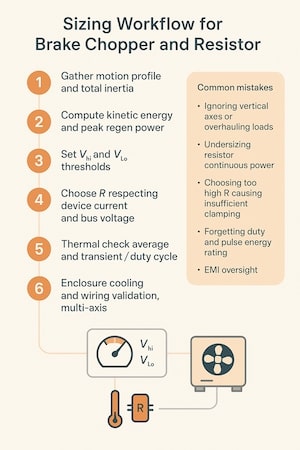
Figure 4. A step-by-step workflow for correctly sizing a brake chopper and resistor, along with common mistakes to avoid in regenerative motion systems. Image used courtesy of Bodo’s Power Systems [PDF]
2. The 6 cost drivers: power level of axis or bus, duty cycle and thermal class required, enclosure and IP rating for the environment, certification and safety documentation, cabling and installation complexity, commissioning effort including EMC testing and tuning.
What are the most common EMI pitfalls on the DC link?
The most common EMI pitfalls increase radiated and conducted noise, raise fault rates, and risk noncompliance. Problems usually start with geometry and end with measurement shortcuts that hide root causes. Long parallel conductors form antennas, high ESL placement creates ringing, and shield terminations done as an afterthought let common mode currents roam through everything else. Team skills vary, and cabinet constraints are real. A short checklist of mistakes can prevent weeks of trial and error.
For deeper design examples and test-based discussions of these topics, industry coverage from Bodo’s Power Systems provides context on switching devices, layouts, and EMI troubleshooting that pairs well with the practices below.
1. Do not route long, untwisted DC bus leads that create a large loop area, which radiates strongly
2. Do not ignore common-mode currents that couple through stray capacitances to the chassis
3. Do not allow ringing from high ESL layouts that amplify switch node transitions
4. Do not let fast edges exceed EMC limits without adding snubbers or filters
5. Do not break shields or float panels, which undermines a low impedance ground bond
6. Do not share long DC buses between axes without dv dt control or local film caps
7. Do not mount the resistor so far away that hot loops and magnetic fields grow uncontrolled
How to mitigate EMI on regenerative systems?
Mitigation is a process that begins with geometry, then adds selective components, and ends with proof on test instruments. This how-to has 8 steps that move from placement to measurement so you can catch issues before compliance day. Start small with the loop area and bond quality. End precisely with probes and pre-scan data so you know what frequency bands matter.
1. Minimize loop area by keeping positive and negative bus conductors close and short
2. Add film capacitors near switching devices to provide a low ESL local energy path
3. Select snubbers or RC damping sized from the measured ringing frequency and impedance
4. Apply common-mode chokes or dv dt filters on motor outputs when cable lengths are long
5. Terminate shields 360 degrees to the chassis at a defined point or per vendor guidance
6. Bond all grounds with low impedance straps or copper so returns are not forced through signal paths
7. Separate power conductors from control wiring and cross at right angles when required
8. Validate with a scope and a simple pre-compliance scan so fixes are based on data, not guesswork
9. Probe points to prioritize: DC bus ripple at the caps, inverter switch node, braking resistor leads during chopper events, chassis bond near the filter entry
Table 1. Brake chopper vs active front-end regeneration.
| Factor | Brake chopper | Active front end |
| Efficiency | Low during braking because energy is dissipated as heat | High because energy is fed back to the grid |
| Capex | Low initial cost for the module and the resistor | High initial cost, including filters and protection |
| Wiring and commissioning | Simple wiring and straightforward setup | Complex wiring and commissioning expertise required |
| EMC impact | Local hot loops need careful layout and snubbing | Line-side emissions require filters, but motor-sideemissions can be calmer |
| Best use cases | Intermittent or bursty regen and emergency stops | Continuous regen, gravity loads, and energy saving mandates |
| Failure modes | Resistor overtemp, transistor failure, open resistor | Tuning errors, grid disturbances, and filter aging |
| Space and thermal | Small footprint, but needs airflow for the resistor | Larger footprint with line reactors and cooling needs |
Conclusion
DC-link management is the quiet heart of a reliable regenerative servo system. The DC link shapes how energy moves, how fast you can stop, and how often you trip on overvoltage. Brake choppers provide a rugged sink for bursts. Active front ends provide efficiency and power quality for sustained events. Good sizing turns physics into numbers you can buy. Good EMI practice turns numbers into cabinets that pass tests and run clean. If you put these ideas into your next design review, you will harvest the energy you already paid to spin up, and you will ship a machine that stops hard, stays up, and sounds civilized.
This article originally appeared in Bodo’s Power Systems [PDF] magazine.