Facebook
 Google
 GitHub
 Linkedin
High-Voltage IGBT Modules for High-Power High-Reliability Applications
When it comes to high-power applications with highest reliability requirements, HV-IGBTs in the famous std-type package are still the favorable choice. This article explains the reasons and how this traditional package is raised to the next level by a variety of innovative technologies.
In the second half of the 1990s, development and commercialization of IGBT power modules for high voltage ratings as 2500 V and 3300 V has started. Originally, these HV-IGBTs were designed as GTO replacement for high-power and high-reliability applications like for example railway traction inverters [1]. Additionally, the use in many other high-power applications has followed.
The device package, which has been used back then, already had the same outline like today’s HV-IGBT power modules. It is the wellknown std-type package with a rectangular footprint of 190 mm times 140 mm.
The advantage of the std-type package is the huge current capacity. Moreover, as single-switch device, it offers great flexibility for complex converter topologies. Therefore, MITSUBISHI ELECTRIC develops power modules in the std-type package further and includes latest chip and package technology.
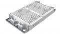
The newest std-type power modules with state-of-the-art X-Series chip set are now available for voltage classes from 1700 V to 6500 V. Figure 1 shows the different std-type packages. This article reveals why and for which applications MITSUBISHI ELECTRIC has developed these power modules. Efficiency, power density and robustness of these power modules increased compared to previous generations. We will have a look at the key-enabling technologies for this improvement.

(a) Insulation voltage 6 kV.

(b) Insulation voltage 10.2 kV.
Figure 1. std-type package with latest X-Series chip technology with 190x140mm² and 130x140mm² footprint packages. Image used courtesy Bodo’s Power Systems
Applications Dedicated to std-type HV-IGBTs
HVDC
Considering bulk-power electricity transmission, high-voltage DC (HVDC) systems based on IGBT power modules have become a mature technology. They allow more compact plant design and more flexible operation compared to the classical thyristor-based transmission systems [2]. In state-of-the-art HVDC systems, DC transmission currents reach 2 kA and beyond [3] [4].
STATCOM
The share of renewable energy sources in our electricity network is steadily increasing. At the same time, related to the goal for CO2 reduction, the share of coal generation is decreasing. The loss of inertia by large generators together with the fluctuating power generation from renewables make stabilization of the electricity network more difficult. STATCOMs (Static Synchronous Compensators) are able to stabilize the network by providing reactive power, active filtering capability, flicker reduction or frequency stabilization. MMCbased [5] STATCOMs are highly modular. Single converter branches can provide inductive or capacitive reactive power of ± 400 MVA for example [6].
Medium-Voltage Drives
Medium-voltage (MV) drives allow the speed control of high-power motors and generators in the voltage range of 3.3 kV or higher. These drive systems are used for offshore wind generation, mills, conveyor belts, compressors or ship propulsion. Usually, these drives have high reliability requirements. Bidirectional power flow for recuperating electric energy is often mandatory. For such MV drives, multilevel converter topologies are frequently used, like 3-level NPC converter [6] or other 5- or 7-level topologies. All above applications have in common that they require IGBT power modules with high current capability. Moreover, end-customers have highest expectations about converter reliability and robustness of semiconductor power modules within. Especially when considering 3-, 5-, or 7-level converter topologies, the busbar design becomes challenging. Hence, the semiconductor power modules should provide as much freedom as possible when designing the converter. The three examples above show that std-type packages are still the first choice for many applications. The std-type packages enable large output currents as 2400 A in the 130x140 mm² package. Moreover, the package outline itself has proven its suitability in decades of field operation. The std-type package originally features “1-in-1” single-switch power modules. The single-switches allow maximal freedom in the converter design which is particularly important for multi-level topologies.
Another use is the development or refurbishment of existing converter platforms. Outline of the new std-type power modules is compatible with previous power modules generations. Therefore, changing to a newer IGBT generation is easily possible. Newer IGBT generations allow higher output current, higher power cycling capability or robustness against humidity. Figure 2 illustrate the possibility to increase the output current by 50 % or reduce size to 2/3 with the new X-Series.

Figure 2. Output current and compactness improvement of new X-Series compared to previous H-Series. Image used courtesy Bodo’s Power Systems
Technical Features of X-Series std-type Power Modules
CSTBT (III) and RFC diode
The current generation of high-voltage power modules has utilized all advantages of 7th generation chips using CSTBT (III) (Carrier Stored Trench-Gate Bipolar Transistor) structure of IGBT and RFC (Relaxed Field of Cathode) structure in the free-wheel-diode. Both chip technologies allow combination of reduced steady state loss, switching loss and robust switching performance. Both chip technologies shift the boarders of technology triangle considering robustness, low total power loss and wide SOA.
The CSTBT is a trade mark of MITSUBISHI ELECTRIC. The CSTBT technology is to be considered as improved technology of trench structure of IGBT. The trench architecture in power devices is introduced by MITSUBISHI ELECTRIC in 1994 allowing reduction of ON-state voltage and endurance property for latch up vs. planar IGBT [7]. The main gain by using of trench IGBTs is elimination of the parasitic JFET resistance. This technological step in combination with LPT (light punch through) technology allows significant drop of VCE(sat) value in IGBT.
The CSTBT forms the n-layer under p-base between trenches, the n-layer stores carriers; as result, the carrier distribution of the CSTBT becomes that of the diode. The density of minority chargers increases, allowing recombination, allowing further reduction of steady state loss [8]. Figure 3 represents the differences between conventional trench technology and CSTBT proposed by MITSUBISHI ELECTRIC. The semitransparent n-buried-layer increases the concentration of minority charges in n-layer.
The CSTBT (III) development is further improvement of CSTBT technology with focus on turn-off loss reduction and uniformity of characteristics like VGE(th) distribution [9]. This improvement allows further utilization of Si material before substitution by SiC power devices.

Figure 3. CSTBT in comparison to conventional IGBT. Image used courtesy Bodo’s Power Systems
The other contribution for efficiency and reliability increase is considered by development and utilization of RFC technique in antiparallel free wheel diode. The dynamic ruggedness and recovery softness are two characteristics which are achieved by introduction of a “Light Punch-Through (LPT) II” and a “Controlling Carrier-Plasma Layer (CPL)” [10] [11] [12]. The Figure 4 shows realization of LPT II buffer on back side pattern which mainly construes to the softness of diode, to improvement of EMC behavior and finally to ruggedness of the total power module.

Figure 4. Structure of RFC diode. Image used courtesy Bodo’s Power Systems
RBSOA Capability
One of the critical events for HVIGBT is turn-off event. Therefore, a wide turn-off safe operating area, so called RBSOA (Reverse Bias Safe Operating Area), is desired. Usually, the maximum specified turn-off current is twice rated current as mentioned in the datasheet. In order to secure low FIT rate in so called “useful life” of the bathtub curve of the power module, the actual turn-off capability must be higher than specified value. The following example demonstrates how big the margin between specification and actual capability is. In this example, turn-off event in one segment of a 6500 V power module with rated current of 330 A is used. Figure 5 represents such event showing turn-off current of 2000A under worst case conditions of Vcc = 4500 V; Tj = 150°C. The factor between RBSOA specification (330Ax2) and actual turn-off capability is 3. Similar RBSOA margin by using of 1000A/6500V power module CM1000HG-130XA is reported in [13], showing margin factor of 4.

Figure 5. Turn-off switching waveform (green: VGE 10V/div, blue: IC 500A/div, red: VCE 1000V/div, time: 2μs/div). Image used courtesy Bodo’s Power Systems
Short Circuit Robustness
To increase converter robustness and decrease downtime after a failure, IGBT power modules usually require short circuit withstand capability. However, not every short circuit has same impact on the power module. Different classifications are done. For example, short circuit type 1 is present when the short circuit occurs before the IGBT turns on. On the contrary, a short circuit type 2 appears when the IGBT has already been turned on and is conducting current [14].
Figure 6 shows the test setup for testing short circuit type 2. IGBT 1 is constantly turned off and only used for freewheeling. IGBT 2 is the actual device under test (DUT). IGBT 3, the “short-circuiter”, emulates the short circuit together with the short circuit inductance LSC, which is substantially lower than the load inductance Lload. To begin the test, the DUT is turned on to ramp up the current. When the desired testing current is reached, the short-circuiter is turned on causing a steep current rise. After a specified time, the DUT is turn-off. The current stored in the inductances LSC and Lload freewheels through IGBT 1. When the currents reaches zero, the test ends.
Figure 7 demonstrates the withstand of a 6.5 kV power module. The test utilizes one of three segments of CM1000HG-130XA. Hence, one segment corresponds to a rated current of around 330 A. The short circuit appears when the IGBT segment already conducts 3-times rated current, means 1000 A. During the short circuit the current rises up to almost 4 kA when the IGBT desaturates and limits the current. After 10 μs, the DUT successfully turns off the short circuit and keeps alive. This test demonstrates once more the high ruggedness of the X-Series power modules.
Power Cycling Capability
Even though X-Series std-type power modules look similar like previous generations from the outside, they include many technical improvements in the inside. Many of these improvements target the increase of power cycling capability.

Figure 6. Short circuit type 2 test setup. Image used courtesy Bodo’s Power Systems

Figure 7. Withstand of short circuit type 2 using one of three segments of CM1000HG-130XA (conditions: Vcc=4200V, Tj =150°C, VGE=15V, tw=10μs, Ic (before short circuit)=1000A (3·Inom). Image used courtesy Bodo’s Power Systems
Compared to previous generations , the X-Series uses a high-temperature solder for the die bonding. Also the solder for attaching the substrate to the baseplate has been improved together with a change of the ceramic metallization. Finally, using improved gel material enabled further increase of power cycling capability. Power cycling tests as exemplarily given in Figure 8 have been conducted. It has been confirmed that the combination of the new package technologies has enabled a 2.7-times improved power-cycling capability compared to the previous generation [15].

Figure 8. Power cycling confirmation test of 3.3 kV X-Series device and previous generation [15]. Image used courtesy Bodo’s Power Systems
Humidity Robustness
In last decade, the impact of environmental factors like humidity, temperature and pollution on reliability of power devices has become a major topic for outdoor applications where such factors can’t be controlled. In this chapter ruggedness of power device on humidity stress is described. The necessity of such ruggedness is described in [16] [17].
The silicone gel is the most popular encapsulation material in power devices. The presence of humidity in silicone gel and applying of relatively high voltages provoke building of dipoles, so called surface charges Qss. The amount of Qss has significant impact on efficiency of chip guard ring and finally on avalanche voltage. Figure 9 shows the relationship of surface charges and blocking voltage capability of 6.5 kV IGBT chip [18]. The reduction of voltage capability by humidity could lead to catastrophic and unpredicted failures which is to be avoided. The immunity against humidity could be reached by influencing of capsulation material, chip structure and passivation material [18]. The intrinsic immunity of power chip by designing of dedicated chips structure is the key step to minimize influence of humidity on reliability of power device. In 2015 MITSUBISHI ELECTRIC has proposed SCC technology (Surface Charge Control) [19]. Figure 10 shows the concept of SCC technology. It uses a semi insulation layer instead of an isolated layer under the passivation. This technology allows reduction of stray capacitance and plays an important role as carrier path. Under electrically biased conditions, carriers generated by the high electric field accumulate at the interface between the silicon surface and the semi-insulated layer as well as the conventional layer. However, the carriers are swept away through the optimized semi-insulated layer simultaneously as shown in Figure 10. There is the temperature dependences of the leakage current density. At room temperature, the SCC type has slightly higher leakage current density than the type without the SCC due to an additional leakage current through the semi-insulated layer. On the other hand, in the high temperature region the SCC type has the superior characteristics because the semi-insulated layer redistributes the electric field optimally in the edge termination area [19]. The verification of robustness degree could be done by test proposed in [18] (cf. Figure 11). This test provoke dew condensation which is the highest humidity stress within a power module. A new automatic condensation test approach was proposed by Mitsubishi Electric to perform the cycling condensation test more efficient using the humidity chamber [20]. This automatic test is helpful to derive the acceleration factors between the field conditions and the hard qualification tests. Furthermore, the lifetime model was proposed in [21] in order understand the influence of humidity and temperature variation at certain humidity on degradation of power module.
Nowadays the reliability test combined three stress factors temperature, humidity and electrical field so called H3TRB is a standard high acceleration reliability test at MITSUBISHI ELECTRIC before releasing of HV power modules. Comparing the X-series with conventional design at 85°C/85%RH an improvement by more than 100 times was confirmed by testing. From these H3TRB test results an unprecedented robustness against 8000 condensation events under IEC 60721-3-5 5K2 reference conditions can be derived for the X-series [22].

Figure 9. Relationship between surface charge Qss and blocking capability. Image used courtesy Bodo’s Power Systems

Figure 10. Concept of Surface Charge Control (SCC). Image used courtesy Bodo’s Power Systems

Figure 11. Condensation test procedure. Image used courtesy Bodo’s Power Systems
Line-Up
The overview of X-Series power modules is given in Figure 12. The X-Series contains devices with blocking voltage ratings 1.7kV, 3.3kV, 4.5kV and 6.5kV. The focus in development priority is set on power modules with highest current ratings utilizing the package with the biggest footprint 140x190 mm². But also power devices in so called middle package 130x140mm² is developed. Now, at least power modules in two different packages with same current rating are available. This development is done based on thermal design consideration. Power devices according to Figure 12 have finished development and successfully passed all reliability tests. The test reports are available on request. All used packaging material are in line with European Railway Standard for Safety EN45545.

Figure 12. Line up of X-Series HVIGBT power modules *Product under development. Image used courtesy Bodo’s Power Systems
This article originally appeared in Bodo’s Power Systems magazine.