Facebook
 Google
 GitHub
 Linkedin
National Electrical Code 2023 Basics: Overvoltage Protection Part 1
Learn about the fundamentals of overvoltage protection – the foundations for an effective protection strategy.
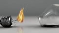
Transient events can harm electric and electronic equipment, causing costly downtime. Overvoltage protective devices limit the transient voltages and divert the currents back to their source or the ground.

Image used courtesy of Pixabay
Protecting Against Transient Overvoltages
Transient overvoltages are short-term deviations from desired voltages or signal levels that vary in frequency, amplitude, and duration. A transient overvoltage on an AC line is large in magnitude and short in duration. The amplitude may reach kilovolts in microseconds.
Transient overvoltages can be positive or negative polarity and may travel through the ungrounded, grounded, and grounding conductors.
Semiconductor equipment is particularly vulnerable to transient overvoltages, and special devices give protection by reducing the transient amplitude and diverting the current.
The concept of protecting electronic equipment is relatively new. Transient Voltage Surge Suppressors (TVSSs) were first manufactured in the late 1970s and early 1980s. The NEC 2002 incorporated Article 285 TVSS.
The NEC 2020 combined Articles 280 (Surge Arresters, Over 1 kV) and 285 (Surge-Protective Devices (SPDs), 1 kV or Less) into Article 242 (Overvoltage Protection).
Figure 1 shows a typical transient overvoltage.

Figure 1. Typical transient overvoltage. Image used courtesy of Lorenzo Mari
Approximately 30% of transient overvoltages originate externally and 70% internally – this ratio may overturn in an outdoor setting.
External Sources of High Energy
The primary external sources of high energy are:
- Lightning strikes
- Switching operations – gensets, smart grid, wind turbine, photovoltaic
- Electrostatic discharges (ESD)
Lightning strikes make up a considerable proportion of the external sources.
A few consequences from the external sources are:
- Catastrophic equipment failure
- An abrupt stop of the operation
- Repairs and replacements of expensive equipment
Internal Sources of Low Energy
Some internal sources of low energy are:
- SCR-controlled equipment
- Photocopiers
- Printers
- Elevators
- Welding machines
- Switching – electric motors and generators, faults, air-conditioning, fuse, and circuit-breaker operation
- Other manufacturing and office equipment
Some consequences of the internal sources are:
- Cumulative damage
- Premature equipment failure
- Data loss
- Computing glitches and errors
- An abrupt stop of the operation
Coupling Modes
Transients can infiltrate equipment through various coupling modes:
- Galvanic
- Inductive
- Capacitive
- Resistive
Galvanic Mode. Galvanic coupling is a direct metallic connection. Examples are lines struck by lightning and electrical faults.
Inductive Mode. Inductive coupling occurs when the magnetic field of a current-carrying conductor induces a current in an adjacent conductor.
Lightning radiates electromagnetic fields with strengths of many kV/m at long distances. These electromagnetic fields may induce high voltages and currents in electric lines.
Power lines near communications, instrumentation, or control lines may induce transient overvoltages.
Capacitive Mode. Capacitive coupling occurs when the natural capacitance between conductors couples the transient.
Resistive Mode. Resistive coupling occurs when lightning in the surroundings generates potential differences between the various ground connections – due to increases in the earth’s potential.
Lightning bolts are so powerful that they couple vast amounts of energy to nearby circuits by the four modes.
A cloud-to-cloud discharge can induce a surge of 7 kV/m in power and telephone cables.
A lightning strike on a line can bring a surge between 10 kV and 20 kV to the building. However, a typical value typically considered for testing is 6 kV, with currents up to 3 kA.
The internal sources can produce hundreds of volts.
Transient Overvoltages Due to Electrostatic Discharges
The discharge of static electricity between two conductors produces a spark – when the charges accumulated on conductive objects create an electric field exceeding the atmosphere’s electric strength.
An example is a spark jumping from a finger or key to a grounded object after walking on a carpet.
A discharge of static electricity may reach 10 000 mJ. An energy value of 0.2 mJ may damage electronic equipment and pose an ignition hazard in the presence of flammable atmospheres – although it is commonly below the threshold of human visual and auditory perception.
The voltage designates the charge strength. A human body can reach a few hundred volts in a wet environment and 10 kV or more in a dry climate.
Impact of Wiring Impedance on Transient Overvoltages
The impedance of the building wiring limits the magnitude of the current reaching the equipment.
The service equipment can withstand 3 kA. The feeders and branch circuits have a high impedance and may limit the current to around 200 A.
As you might expect, the breakdown of insulation, switches, and other components will limit the magnitude of the transient voltage in the building’s distribution system.
Dielectric Tests
Abnormal voltages cause premature failure of the insulation. “Insulation withstand” is the voltage tolerated by the insulation of the equipment without failing.
Although actual transients do not always resemble the models for testing, there are standards such as the IEEE, UL, and the IEC to determine the immunity of electrical and electronic equipment to surges.
A standard test is the Basic Lightning Impulse Insulation Level (BIL) – the BIL is the full-wave test.
The standard voltage surge has a 1.2/50 µs (T1/T2 µs) waveshape with a specified crest kV.
It means the voltage surge rises from zero to the crest value in 1.2 µs and falls to half the crest value in 50 µs. This waveshape imitates a lightning surge. See figure 2.

Figure 2. Standard 1.2/50 µs voltage wave, delivered across an open circuit. Image used courtesy of Lorenzo Mari
The practice finds a virtual zero time by locating the points on the wavefront where the voltage is 30% and 90% of the crest value and drawing a straight line through these points. The zero virtual time (t0) is the intersection of this line with the time axis.
T1 is the time from virtual zero to a point determined by the intersection of the straight line with a horizontal line at the crest voltage value.
T2 is the time from virtual zero to half the crest value at the tail of the wave.
Therefore, T1 = 1.2 µs is the wavefront duration, and T2 = 50 µs is the time from virtual zero to half crest value.
For example, a 6 kV, 1.2 x 50 µs impulse wave reaches a peak of 6 kV at 1.2 µs (wavefront) and decays to 3 kV (half crest value) at 50 µs after t0.
Crest values are classified into discrete values. A given rated voltage may have more than one BIL level.
Lightning currents also vary over a wide range.
The industry standard current surge has a waveshape of 8/20 µs (T1/T2 µs), as shown in figure 3.

Figure 3. Standard 8/20 µs current wave, delivered into a short circuit. Image used courtesy of Lorenzo Mari
The above description involves specific dielectric tests. The standards for individual types of equipment detail the precise tests and methods that apply to the apparatus under test.
The Function of Overvoltage Protective Devices
The purpose of overvoltage protective devices is to prevent exceeding the withstand capacity of the system and equipment. Any time a surge tries to exceed the insulation’s capability, the protective devices will keep the voltage in the acceptable range, protecting the electrical apparatuses.
Overvoltage protective devices are typically connected in parallel to the protected equipment and are subjected to the rated system voltage under normal operating conditions.
Under steady-state conditions, their impedance is very high. The impedance decreases sharply at higher voltages when a wavefront enters the system, deflecting the portion of the wave above their breakpoint to the ground, away from the downstream protected equipment.
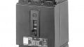
Figure 4 shows a typical SPD protecting a piece of electronic equipment.

Figure 4. An SPD protecting electronic equipment. Image based on MCG Surge Protection and used courtesy of Lorenzo Mari
Metal oxide varistors (MOVs) are typical components utilized in SPDs. They display a non-linear volt-ampere characteristic – usually made with zinc oxide. Their thickness regulates the clamping voltage, and the diameter governs the current capacity.
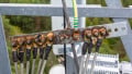
Figure 5 shows a typical Surge Arrester protecting a piece of power equipment.

Figure 5. A surge arrester protecting power equipment. Image used courtesy of Lorenzo Mari
For the overvoltage protective devices to adequately protect equipment, the voltage they see before and after the arrival of the surge must not exceed the voltage that the equipment can handle.
In addition to maintaining the voltage at an acceptable level, a vital factor is the capability to store or dissipate energy without damage.
The amount of energy absorbed by the devices depends on the magnitude and duration of the surge.
Under steady-state conditions, the impedance of the devices should be high enough to draw little current and dissipate minimal power.
Useful Definitions Related to Surge Protective Devices
Nominal System Voltage: The rated voltage of the protected system.
NEC Section 242.12(1) prohibits the installation of an SPD on circuits above 1 kV.
Maximum Continuous Operating Voltage (MCOV): The maximum designated RMS value of the power frequency voltage that may be continuously applied to the mode of protection of an SPD – the maximum allowed voltage before the SPD will start to clamp.
Typical MCOV figures range from 15% to 25% above the nominal system voltage.
Section 242.12(3) prohibits the installation of an SPD where its rating is less than the maximum continuous phase-to-ground voltage at the power frequency available at the point of application.
Nominal Discharge Current (In): Crest value of the current – selected by the manufacturer – through the SPD having a waveshape of 8/20 µs where the SPD remains functional after 15 surges – In tests the SPD strength.
The standard crest values for testing are 3 kA, 5 kA, 10 kA, and 20 kA.
Voltage Protection Rating (VPR): The average limiting voltage of an SPD when exposed to a 6 kV, 1.2/50 µs, 3 kA, 8/20 µs (combination wave) with a combination generator – the VPR tests the clamp voltage.
Short-circuit current rating (SCCR): The fault current level to which an SPD can be subjected and safely disengage from the circuit.
Section 242.8 requires the SPD to be marked with a short-circuit current rating and prohibits its installation at a point where the available fault current exceeds this rating.
Clamp Voltage: The crest Metal Oxide Varistor (MOV) terminal voltage measured with a standard 8/20 µs impulse current. It is also named Let-Through Voltage: The amount of voltage the device allows to reach the protected equipment.
Follow-On Current: The current that continues to flow through the device during regular operation after the transient event. It happens when the SPD fails to return to a high impedance state.
Key Takeaways of Overvoltage Protection
- Overvoltage protective devices protect the electrical systems and equipment from transients by limiting voltages and diverting currents.
- Sources of transients can be external – primarily by lightning and switching – or internal – like switching loads, motors, and office equipment.
- An overvoltage protective device must:
○ Show high impedance under steady-state conditions, consuming a small leakage current, if any, and withstand the thermal stress it produces.
○ Withstand the thermal energy generated by the overcurrent through the elements of the device.
○ Restore the steady-state conditions immediately after the overvoltage and the overcurrent disappear.