Facebook
 Google
 GitHub
 Linkedin
Substation Protection Against Transient Overvoltages and Lightning Strikes
Learn how surge arresters protect power substations against lightning and switching overvoltages.
Transient overvoltages are typical of power systems. The sources of overvoltages are direct or nearby lightning strikes, switching operations, electromagnetic pulses, and electrostatic discharges. The classical device to protect equipment in substations against the effects of transient overvoltages is the surge arrester.
The most frequent transient overvoltage in substations comes from switching operations, and the most fearful is lightning, which introduces large disturbances.
Lightning-Caused Transient Overvoltages
Lightning is a prime source of transient overvoltages. In a substation shielded from direct strikes and with relatively low ground resistance, the most likely source of lightning surges is traveling waves entering through the overhead lines.
When lightning strikes an overhead line, it initiates a traveling wave. The traveling wave’s current value depends on the magnitude of the lightning surge, the line surge impedance, and the tower footing resistance. With phase conductors adequately shielded from direct strikes, the leading cause of the traveling waves is insulator flashover; in such cases, the overvoltage magnitude is the insulator flashover value.
Lightning is random, and there is always a possibility that a lightning strike, bypassing the substation’s shield, hits the protected circuits in or close to the substation.
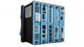
The standard device to protect equipment in substations against overvoltages is the surge arrester. When connected from each phase conductor to the ground, the surge arrester transfers the high surge currents safely to the ground, protecting the system and equipment – such as transformers, circuit breakers, and bushings – insulating against the consequences of overvoltages.
Some Useful Terms
There are many terms in the analysis of power system electrical transients. A few useful terms to be aware of are:
- Power-frequency: 60 Hz or 50 Hz, depending on the country’s standard.
- Flashover: a disruptive discharge around or over an insulator’s surface. Not to be confused with sparkover, which is a surge arrester term.
- Sparkover: a disruptive discharge between the surge arrester’s electrodes. This term does not apply to gapless metal-oxide arresters.
- Power-frequency withstand voltage: the highest rms applied voltage at which an arrester will not flashover.
- Impulse withstand voltage: the highest crest value of the surge voltage at which an arrester will not flashover.
- Power follow current: power-frequency current through an arrester, during and after the passage of surge current. This term does not apply to metal-oxide arresters.
- Arrester voltage rating: maximum power-frequency rms line-to-ground voltage to which an arrester may be exposed, even under transient conditions.
- Arrester discharge voltage: the voltage across the arrester while carrying surge current.
- Arrester discharge current: The current flowing through an arrester, resulting from a striking surge.
- Power-frequency sparkover: the minimum power-frequency rms voltage that will initiate sparkover between the line and ground terminals. This term does not apply to gapless metal-oxide arresters.
- Front-of-wave sparkover: the voltage on the front of an impulse wave, rising at a preset constant rate, at which the arrester sparks over.
- 1.2/50 µs impulse sparkover: the highest impulse voltage that an arrester will allow without sparkover. This term does not apply to gapless metal-oxide arresters.
- Maximum continuous operating voltage (MCOV): the maximum rms power frequency voltage that may be applied continuously between the arrester’s terminals. This term only applies to metal-oxide arresters.
Dielectric Tests
Anomalous voltage stresses cause early insulation failure. Insulation withstand refers to the voltage tolerated by equipment insulation without failure.
Knowing the withstand capability and endurance qualities of the insulation system is vital. Insulation-type designations, as well as high-potential and surge-voltage tests, classify the insulation’s properties and state the withstand capabilities.
Overvoltage tests certify the ability of the equipment insulation to outlive various stress levels after manufacturing completion. The most common tests are:
- Basic Lightning Impulse Insulation Level (BIL)
- Chopped Wave Withstand (CWW)
- Basic Switching Impulse Level (BSL)
- Front-of-wave-test
Let's explore each of these tests a bit more.
Basic Lightning Impulse Insulation Level (BIL)
The BIL is the full-wave test. The standard impulse is a 1.2/50 µs (T1/T2 µs) waveshape, with a crest specified in kilovolts. This means that the voltage pulse increases from zero to crest value in 1.2 µs and declines to ½ crest value in 50 µs. The rise time and duration of this waveshape replicate a lightning surge.
The oscillogram of actual voltage may be challenging to interpret, particularly at the beginning of the waveshape. In this case, the BIL test finds a virtual time zero by locating points on the wave’s front where the voltage is 30% and 90% of the crest value and draws a straight line through these points. The virtual time zero is the intersection of this line with the time axis.
Figure 1 shows the standard 1.2/50 µs open-circuit voltage waveshape.

Figure 1. Standard 1.2/50 µs open-circuit voltage waveshape.
T1 is the time from the virtual zero to a point determined by the straight line’s intersection with a horizontal line at crest voltage value. T2 is the time from the virtual zero to half the crest value on the wave tail.
Therefore, T1 = 1.2 µs is the duration of the wavefront, and T2 = 50 µs is the time from the virtual zero to ½ crest value.
Another way to compute the time to crest is 1.67 times the actual time between 30% and 90% of the crest value. The crest values are classified into discrete values. A given rated voltage may have more than one BIL level.
The lightning strike’s currents also vary over a broad span. The industry standard impulse current is an 8/20 µs (T1/T2 µs) waveshape, as shown in Figure 2.

Figure 2. Standard 8/20 µs impulse current waveshape.
Another way to compute the time to crest is 1.25 times the actual time between 10% and 90% of the crest value.
Chopped Wave Withstand (CWW)
The waveshape for this test is the same used to determine the BIL, but it collapses at a time t – specified in the standard – after the wave’s crest by sparkover of an external rod gap shunting the tested equipment. The crest voltage is from 110% to 115% of BIL (Figure 3).

Figure 3. Sparkover on the tail.
Basic Switching Impulse Level (BSL)
The BSL test of equipment is similar to the BIL but focuses on switching impulse rather than lightning. The wave shape depends on the tested equipment.
Front-of-wave Test
This test is similar to the chopped-wave test, but the voltage is cut off by a rod gap on the rising front of the wave at a time t rather than shortly after the wave’s crest. The gap limits the voltage to a preset value (Figure 4).

Figure 4. Front-of-wave sparkover.
The previous description involves general principles of dielectric testing. Standards for individual types of equipment detail the precise tests and methods to apply to the apparatus concerned.
Operation Principle of Surge Arresters
Insulation costs are very high, so insulating the system and equipment to resist any voltage that would ever appear is not economically viable. It is also impractical to insulate for steady-state voltage and accept all outages originating from surges. It is reasonable to look for a balance between the costs of insulation and protective devices.
Surge arresters are vital to protect the substations against lightning and switching surges. Their surge protective capability determines the power system insulation levels.
The duty of a surge arrester is to avoid exceeding the system and equipment withstand capabilities. Then, whenever a surge tries to exceed the insulation capacity, the arrester will keep the voltage in the acceptable range, protecting expensive electrical devices.
Surge arresters are generally connected in parallel with the protected equipment and are subjected to the system voltage under normal operating conditions. Under steady-state voltage, their impedance is very high. However, it decreases abruptly at higher voltages when a steep wavefront surge comes into the system. The surge arrester diverts the wave’s portion above the arrester breakdown to the ground, away from the downstream protected equipment, as shown in Figure 5.

Figure 5. Operation principle of the surge arrester.
For the surge suppressor to adequately protect the equipment, the voltage that the suppressor sees before and after the surge’s arrival must not overshoot the voltage that the equipment can carry.
In addition to the arrester’s capability to keep the voltage within an acceptable level, a vital factor to consider is its capacity to store or dissipate energy. The diverted current through the arrester and the voltage across it make the device absorb a quantity of energy that depends on the surge’s magnitude and duration. The arrester must store or dissipate this energy without any damage.
Under steady-state conditions, its resistance should be high enough to consume little current and dissipate minimal power.
To summarize, a surge arrester should:
- Display a high resistance under steady-state conditions, consuming a small leakage current – if any – and withstand the thermal stress it produces.
- Protect against an overvoltage, discharging the surge current immediately and limiting the voltage within a specified upper value – the arrester discharge voltage.
- Withstand the thermal energy generated by the surge current through the arrester elements – the arrester discharge current.
- Restore the steady-state conditions immediately after the surge voltage and current disappear, and interrupt the follow current.
- Possess switching surge discharging capability within specified levels.
- Be capable of discharging transmission lines
Separation Distance in a Surge Arrester
The surge arrester should be as close as possible to the equipment it protects because whatever it lets through before it operates will reflect with the same polarity– the equipment’s surge impedance is usually much greater than the line’s surge impedance (Figure 6).
If there is a large separation between the equipment and the surge arrester, the terminal voltage can reach a high value before being reduced by a reflection from the arrester.

Figure 6. Surge arrester separated from a transformer. Image courtesy of McGraw-Edison Company.
Keeping the surge arrester’s leads short reduces their inductance. We must avoid a situation in which the action of a surge arrester is nearly blocked or drastically delayed by the lead’s inductance.
A Review of Substation Protection Against Transient Overvoltages
A surge is a temporary steep rise of voltage in a power system, usually due to lightning or internal causes – mainly switching maneuvers. The energy contained in a surge may cause the failure of insulation in electrical systems and equipment unless they are correctly protected.
Surge arresters protect power substations by limiting lightning and switching overvoltages to a specified protection level below the insulation withstand voltage.
Surge arresters have non-linear voltage and current characteristics, allowing them to start conduction at a specified voltage level, hold the voltage for the overvoltage duration, and stop conduction when the voltage returns to steady-state conditions. The arresters absorb or dissipate the overvoltage energy, as well.
The dielectric tests verify the ability of the system and equipment insulation to withstand various forms of surges.
In the next article, we dive deeper into the features and characteristics of different surge suppressors by exploring their materials, topographies, and applications.