Facebook
 Google
 GitHub
 Linkedin
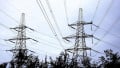
Understanding the Interaction between Lightning and Power Transmission Lines
Learn about the impact lightning strikes have on transmission lines and proper grounding’s role in lowering the chances of irreversible damage to a power system.
Lightning disturbances are usually a significant issue for transmission lines up to the highest voltages. Over time, there have been numerous studies on the impact that lightning strikes have on transmission lines’ performance to increase the knowledge about the subject and reduce service interruptions.
This article looks at those studies and explores how lightning affects the performance of transmission lines.
Closing the Electric Circuit from Earth to Cloud
The current from the impact of an atmospheric discharge from a cloud must dissipate toward the earth. But how does the electrical circuit close to allow the current to go back to the cloud Assuming that the cloud and the ground form a huge capacitor discharged through the lightning, the return would be through the electric field’s displacement current, shown in Figure 1.
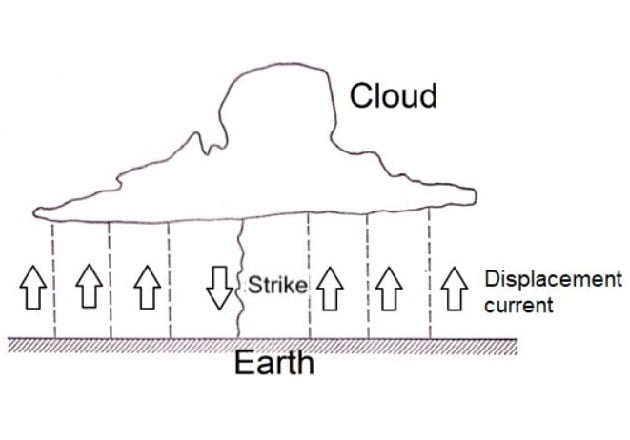
Figure 1. A lightning strike from the cloud to earth and the return current.
This diagram, which represents the lightning path as if it were a solid cable, significantly oversimplifies the phenomenon. A more complete representation must take into account the leader strike and the prestrike. Various studies have analyzed this problem.
The Potential Gradient at Ground
When a charged cloud passes over the Earth, it produces an accumulation of charge on the ground and on objects on the ground below the cloud, such as transmission lines. Figure 2 shows the hypothetical potential gradient over the ground surface, assuming the cloud has a positive charge at the top, a negative charge at the bottom, and a small but dense region of positive charge near the bottom.
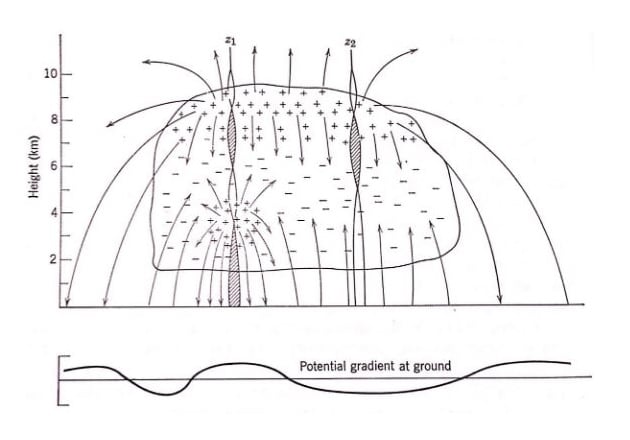
Figure 2. Potential gradient induced at the ground by a cloud. Simpson and Scrase, 1937.
When the charges within the cloud move, so do the charges on the ground. This movement represents a current flow, so momentary potential differences appear between points on the ground. The movement of charges within the cloud is a gradual process unless a discharge occurs, so the ground currents are small.
When the stepped leader gets close to the ground, it drops charge from the cloud. Swift, sudden movements appear in the charges induced on the ground, which become more concentrated as the leader approaches the ground. Still, the currents in the ground, due to charge motion, are small.
Lightning Strikes to the Transmission Line
The lightning strike injects a current into the power system when it hits a transmission line. The magnitude of the generated voltages depends on the current waveform and the impedances through which it flows. The steepness of the voltage wave governs the insulation flashover.
Most critical elements in the analysis of lightning phenomena disappear in a few microseconds. The charge on the leader’s head, its potential, or capacitance are such that they generate the flow of tens or hundreds of thousands of amperes when impacting the power line. Through impedances on the order of hundreds of ohms, these high currents create voltages of megavolts or tens of megavolts. For example, a tower with a surge impedance of 125 Ω, in parallel with two ground wires, might have an effective surge impedance of 75 Ω. A current of 50 kA would produce a voltage on the order of 4 MV.
Once the stepped leader establishes a channel to the ground, the return strike represents a progressive process of neutralizing that channel’s charges. The neutralizing front moves up the channel with a speed of approximately one-third the speed of light. This rate, together with the amount and configurations of the charge to be neutralized, determines the current wave’s magnitude and shape. For example, if the channel contains 1 mC/m and the strike travels at a speed of 100 m/µs, the current would be 10⁵ A.
Suppose that in the initial stages of the lightning strike, not all the neutralizing charge flows from the impacted line. It also comes from the charge in the air adjacent to the prestrike channel. In that case, the initial rate of rise of the current in the return strike through the line may not be as fast as we might think.
Lightning can hit the phase conductor, a ground wire, or the top of the steel tower.
When striking a phase conductor on a highly insulated line without overhead ground wire, the lightning’s voltage could build up to enormous values.
If lightning strikes the ground wire, the impedance through which the current acts is much lower, and flashover requires a higher current. When the strike is in midspan, the current divides and flows toward both towers; the current divides again at the tower, moving between it and the outgoing ground wire.
If lightning strikes the top of a tower, the tower and ground impedances are the most important factors that influence the lightning-induced voltage. The voltage drop originating in the tower appears across the insulation of the line. If this voltage is excessive, it will create an insulation flashover and generate a fault in the system.
A portion of the current impacting the tower’s top flows through the ground wires, and the remainder goes down the tower towards the earth. The tower’s impedance appears in parallel with the ground wires’ surge impedance, reducing the total impedance and, consequently, lowering the voltage at the top.
When the tower impedance and tower footing resistance are low and the strike is moderate in terms of current magnitude and rate of rise, the current flowing down the tower passes harmlessly towards the ground. But if the impedance is high or the strike is more severe, the current flow through the tower produces a voltage that may be high enough to initiate an insulation flashover from the tower to one or more phase conductors.
Midspan flashovers rarely occur. Usually, the breakdowns are through the insulators on the towers.
Also, keep in mind the substantial electric and magnetic couplings between the ground wires and phase conductors, which limit the voltage between them and reduce the likelihood of flashover.
There is no problem if the voltage at the top of the tower is high as long as it also increases in the phase conductors at the same rate.
Current and Voltage as Traveling Waves
When lightning strikes the ground wires or phase conductors, the current splits in both directions and the lightning current meets the wire’s and conductor’s surge impedances, producing a voltage. Both current and voltage flow as traveling waves along the wire.
A tower represents a discontinuity to the traveling waves of current and voltage circulating through the ground wires, whereby these waves are reflected and refracted.
The reflected wave returns towards the point where the lightning struck. There are two refracted waves — one refracted wave travels to the next span of the ground wire while the other travels down the tower toward the ground.
If the refracted wave going down the tower encounters a low impedance in the ground, it will reflect upwards with opposite polarity, canceling the incident wave’s potential and reducing the possibility of flashovers. But if the incident wave encounters a high impedance to ground, it will be reflected with the same polarity reinforcing the incident wave and increasing the possibility of flashover.
When the lightning current propagates in both directions along the ground wire, it induces traveling waves in the phase conductors. For ground wires to be useful, the potential difference built between them and the phase conductors must not be large enough to cause flashover between them. If this occurs, it will generate a line-to-ground fault to be cleared by the switches at the end of the line, producing an outage.
A multitude of quickly generated waves complicates the analytical study of the problem. The line behavior analysis requires sophisticated computer software and physical scale models of lines.
The traveling waves flowing along the phase conductors eventually reach a terminal point where they impact the electrical devices connected to the line. The attenuation through the line has an important role, such that only impacts close to electrical equipment may cause damage. Surge-protection devices also provide protection.
The speed of the traveling waves is close to the speed of light. If the lines were lossless, the speed would equal that of light. Rough calculations may use a speed of 300 m/µs.
The magnitude of the voltage is equal to the current multiplied by the surge impedance. The surge impedance of an overhead transmission line is 300 Ω to 400 Ω and is almost purely resistive. Ultra-high-voltage (UHV) lines with bundled conductors may have lower surge impedance.
Electrostatically and Electromagnetically Induced Charges
As mentioned above, a passing charged cloud produces an accumulation of charges on the ground. If there is a transmission line in the electric field between cloud and earth, it induces opposite polarity charges on the line conductors and ground wires. These bound charges accumulate on the phase conductors by leakage over the insulators and traveling in from the conductors beyond the cloud’s influence. Charges accumulate more easily on the ground wire by direct migration up the towers from the ground.
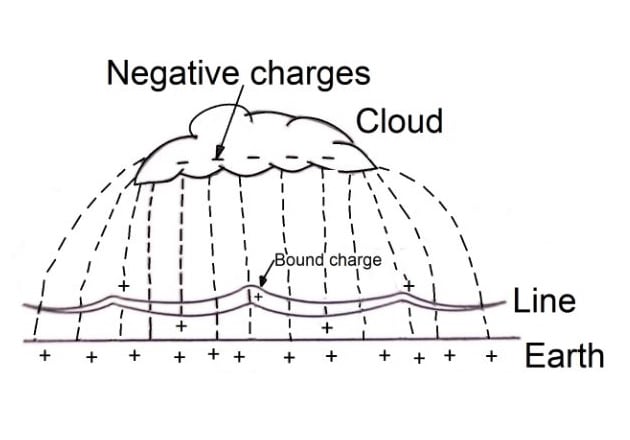
Figure 3. Cloud electric field and bound charge on the ground and transmission line.
If a lightning strike occurs from the cloud to ground near the transmission line, the cloud field collapses and releases the bound charges traveling in both directions. The phase conductors’ bound charges move as traveling waves and the ones from the ground wires move as straight discharge currents.
The charge on the ground wires goes down the adjacent towers and the charge on the phase conductors travels along the conductors and dissipates gradually in corona and resistance loss. These electrostatically induced lightning surges are relatively harmless.
The severe surges to worry about are the electromagnetically induced ones resulting from lightning strikes impacting near the line without directly hitting it. These surges are capable of producing flashovers.
Factors for Good Line Design
It is fundamental to understand the factors that influence the line performance to reduce lightning strike risk. The purpose of good line design is to minimize the faults caused by lightning strikes.
The design is a compromise as needs in one area frequently conflict with other requirements, including economics. For instance, underground lines are immune to lightning strikes. However, it is not economically feasible to build all lines underground.
A lightning strike to a transmission line is a statistical event, and lightning events can vary widely from year to year. Determining the real lightning performance of the line requires many years of exposure.
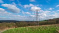
The first step in a line design is to minimize the incidence of lightning strikes on the line and the effects of the strikes that reach it. The incidence of lightning in the areas where the line passes is significant.
Experience shows that lightning mainly strikes tall objects, so towers are more vulnerable than poles. However, adequate clearance cannot be maintained with low structures without reducing the span, increasing the number of required structures and the cost.
The method of installing ground wires to reduce outages works quite well as long as they are correctly located relative to the phase conductors and have adequate clearance from the phase conductor — not only at the towers but also throughout the span. Their position strongly affects the degree of protection.
Overhead ground wires perform three functions:
- Intercepting the direct strike and keeping it off the phase conductor (i.e., shielding)
- Distributing the current in several paths, reducing the voltage drop
- Reducing the voltage induced on the conductors from nearby strikes
According to Lacey (1949), the ground wires adequately protect the phase conductors below a quarter of the circle drawn with its center at the ground wire’s height and a radius equal to the ground wire’s height above the ground.
If installing two or more ground wires, the vulnerable area between two adjacent wires is the semicircle whose diameter connects the two ground wires, as shown in Figure 4.
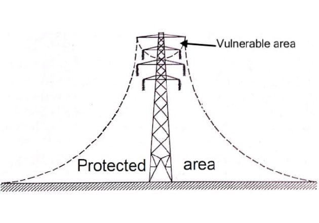
Figure 4. Protection provided by ground wires. Lacey, 1949.
Ground wires increase the number of strikes that terminate somewhere on the lines without increasing the number of outages.
Ground wires suitably situated may intercept more than 95% of the strikes which would otherwise reach a phase conductor. But lightning doesn’t always follow a straight vertical path to the ground and may pass the ground wire and hit the phase conductor. This event’s likelihood increases during thunderstorms when high winds would blow the phase conductor out beyond the zone of protection of the ground wire.
If tower footing resistances are too high, they must be lowered to a reasonable value with counterpoises or driven rods (Figure 5).
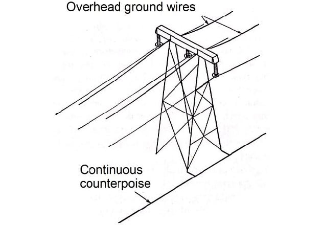
Figure 5. Suspension tower with ground wires and counterpoise.
The system voltage also plays an essential role in the incidence of lightning problems in transmission lines. Generally, the failure rate decreases as the voltage increases due to the larger amount of insulation.
Quantitative results of lightning phenomena analysis are not always accurate due to data uncertainty. Still, such research also generates useful qualitative results for designing the line, such as:
- There is no way to control lightning currents with a high rate of rise, which are more formidable because they produce devastating voltages before attenuation by the reflected waves.
- Avoid high surge impedances in the ground wires and steel tower structure and high ground impedance or tower footing resistance – they increase voltage and outages for a particular lightning exposure.
- Look for a close coupling between the ground wires and phase conductors – it minimizes the voltage between them.
Reviewing the Interaction between Lightning and Transmission Lines
Moving charged clouds lead to an accumulation of charges of opposite polarity on the ground and objects below the cloud. Transmission lines may have bound charges, and electrostatically induced lightning surges occur when they are suddenly released. However, the impact on the power system is low.
Electromagnetically induced surges are the most severe.
Under direct strikes to the line, the voltage rises quickly at the contact point. Current and voltage propagate in the form of traveling waves in both directions. If the voltage exceeds the line-to-ground voltage of system insulation, it can produce an insulation flashover and an outage.
The primary purpose of ground wires is to shield phase conductors, capturing the lightning strikes. The degree of protection depends on the location of the ground wires relative to the phase conductors.
When lightning current travels in both directions along the ground wire, it induces traveling waves in the phase conductors. When a traveling wave reaches the ground through a high inductance tower and the footing resistance is high, a flashover may occur.