Facebook
 Google
 GitHub
 Linkedin
National Electrical Code Basics: Branch Circuits Part 1
Learn about the basics of branch circuits, according to the National Electric Code.
For additional insightful articles on the National Electrical Code and branch circuits, please follow these links:
- National Electrical Code Basics: Branch Circuits Part 2
- National Electrical Code Basics: Sizing and Protecting Branch-circuit Conductors
- National Electrical Code Basics: Computing Voltage Drop in Branch Circuits and Feeders Part 1
- National Electrical Code Basics: Computing Voltage Drop in Branch Circuits and Feeders Part 2
- National Electrical Code Basics: Computing Voltage Drop in Branch Circuits and Feeders Part 3
- National Electrical Code Basics: Feeder and Branch-circuit Load Calculations
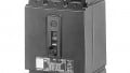
Electric power has to reach the outlets and equipment to be used. A “branch circuit” is the wiring to a group of outlets, a single outlet, or a piece of equipment on a site. The locations may be residential, commercial, or industrial.

Image used courtesy of Pixabay
Definition
According to NEC Article 100, branch circuits are the conductors between the final overcurrent device protecting the circuit and the outlet.
NEC Article 210
This article deals with lighting and appliance branch circuits. Article 210 covers general requirements for branch circuits. The article also covers motors or motor-operated appliances – combination loads – connected to illumination or appliance branch circuits.
NEC Table 210.3 “Specific-Purpose Branch Circuits” lists references for specific equipment. For example, Article 430 covers branch circuits supplying only motor loads.
Article 210 always applies. Yet, specific purpose articles may amend or supplement its rules. Provisions of articles 210 and 430 apply for combination loads.
Types of Branch Circuits
According to the NEC, there are four types of branch circuits:
1. Appliance (2-wire circuit): Supply energy to one or more appliance outlets. They have not permanently connected luminaires unless these luminaires are part of the appliances – e.g., deep fryer, vacuum cleaner, toaster oven, coffee maker, iron, microwave.
2. General purpose (2-wire circuit): Supply energy to two or more receptacles or outlets for lighting and appliances – e.g., table lamp, wall lamp, floor lamp, pendant, and appliances.
3. Individual (2- or 3-wire circuit): Supply energy to one utilization equipment – e.g., refrigerator, freezer, washing machine, dishwasher, oven. As mentioned earlier, Article 430 covers the individual branch circuits of each motor.
4. Multiwire: Supply energy through two or more ungrounded conductors and a grounded conductor. The potential differences between each ungrounded conductor and the grounded conductor (neutral) are equal. Typically supply appliances connected line-to-neutral or line-to-line and line-to-neutral – e.g., clothes dryers and ranges.
Multiwire Branch Circuits
A multiwire branch circuit may be a single circuit or multiple circuits.
Critical rules for a multiwire branch circuit are:
1. Originate all conductors from the same distribution equipment.
2. Provide, at the origin, a disconnecting means to simultaneously open each ungrounded conductor.
3. Supply line-to-neutral loads only, unless
a. The circuit powers a piece of single utilization equipment, or
b. The overcurrent protective device (OCPD) opens all ungrounded conductors simultaneously.
4. Identify or group grounded conductors (neutrals) when they belong to different ungrounded circuits and share the same enclosure. Employ wire markers, cable ties, or similar means in no less than one location within the enclosure. This rule shall not apply when
a. The branch-circuit conductors enter from a cable or a raceway exclusive to the circuit with an evident grouping.
b. The branch-circuit conductors pass through a box or conduit body without a loop, a splice, or a termination.
Typical Low-voltage System Arrangements (600 V and Below)
Systems over 600 V are “distribution systems,” mainly employed in extensive industrial facilities.
Systems of 600 V and below are “utilization systems.” These systems habitually supply power to general-purpose outlets, lighting, and utilization equipment and can be single-phase or three-phase.
1. Single-phase
1.1 120/240 V designates a two-section winding that can be connected either in series for 2- or 3-wire service or parallel for 2-wire service. See figures 1 and 2.
120/240 V provides
- 120/240 V, 3-wire, single phase.
- 240 V, 2-wire, single phase.
- 120 V, 2-wire, single phase (total kVA).

Figure 1. Series 120/240 V system.
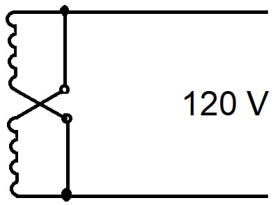
Figure 2. Parallel 120 V system (total kVA).
1.2 240/120 V designates a winding with a center tap for 2- or 3-wire service, with half available power to a single load at the lower voltage. See figure 3.
240/120 V provides
- 240/120 V, 3-wire, single phase.
- 240 V, 2-wire, single phase.
- 120 V, 2-wire, single phase (1/2 kVA).
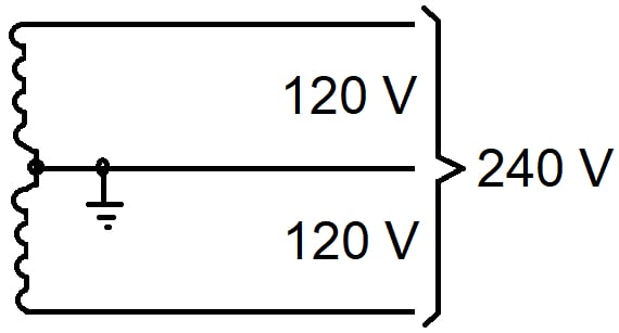
Figure 3. 240/120V system.
1.3 240x480 V designates a two-section winding connected either in series or parallel for 2-wire service only. See figures 4 and 5.
240x480 V provides
- 480 V, 2-wire, single phase.
- 240 V, 2-wire, single phase.
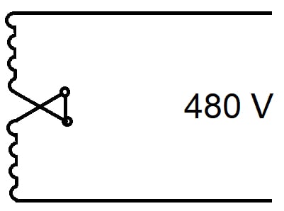
Figure 4. 480 V, 2-wire, single phase.
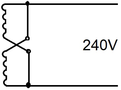
Figure 5. 240V, 2-wire, single-phase.
3-wire service is widespread among single-phase users, like small business enterprises, stores, and dwellings.
2. Three-phase
2.1 208 Y/120 designates wye-connected windings. This scheme is broadly accepted. See figure 6.
208 Y/120 V provides
- 120 V, 2-wire, single phase.
- 208 V, 2-wire, single phase.
- 120/208 V, 3-wire, single phase.
- 208 V, 3-phase.
- 208 Y/120 V, 4-wire, 3-phase.
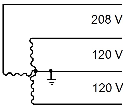
Figure 6. 208 Y/120 V system.
2.2 480 Y/277 V designates wye-connected windings. See figure 7.
480 Y/277 V provides
- 277 V, 2-wire, single phase.
- 480 V, 2-wire, single phase.
- 277/480 V, 3-wire, single phase.
- 480 V, 3-phase.
- 480 Y/277 V, 4-wire, 3-phase.
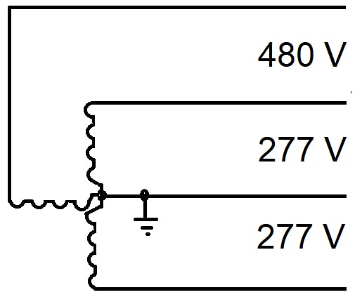
Figure 7. 480 Y/277 V system.
The NEC requires grounding all wye systems when using the neutral as a circuit conductor.
Also, the NEC warns about the danger of overloading the neutral of a 4-wire, 3-phase, wye-connected system when supplying non-linear loads – e.g., adjustable-speed motor drives, computers, and printers – due to the likelihood of high harmonic currents. These harmonic currents appear in phase and do not cancel in neutral but add. This condition might require an oversized neutral or three individual neutrals, one per phase.
2.3 Delta connection.
Windings may be at 240 V, 277 V, 480 V, or 600 V. They provide a 3-phase service by connecting to the three wires and a 2-wire, single-phase service by tying to two of the three wires. See figure 8.
Single-phase 480 V and 600 V are unusual. Yet, they can feed a transformer of a separately derived system.
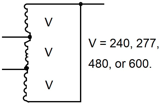
Figure 8. Delta system.
An ungrounded (floating) delta should have a ground indicator to alert maintenance personnel because a second ground may be catastrophic.
A 120 V, 3-phase, 3-wire delta requires the grounding of one of the corners to comply with NEC 250.20(B)(1) and avoid an NEC violation. Such a system changes to a corner-grounded delta.
2.4 3-phase, 3-wire, corner-grounded delta (line grounding).
Grounding one of the corners leads to the so-called “corner-grounded.” This method allows a grounded point on an existing floating delta, obtaining some of the benefits of grounding at minimum cost. See figure 9.
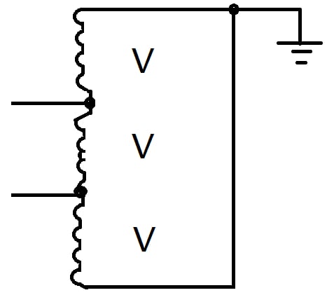
Figure 9. 3-phase, corner-grounded delta.
There is no change in the voltages between wires compared with the delta system. Yet, one wire is at ground potential, and the other two have a voltage of 120, 240 V, 277 V, 480 V, or 600 V to ground. The NEC requires the identification of the grounded wire throughout the network to avoid faulty connections.
For 480 V and higher voltages, sustained arc faults are likely.
New installations should not use this scheme.
2.5 3-phase, 4-wire, delta, with one phase grounded at the midpoint.
When at least one of the single-phase transformers comprising a bank has a mid-tap available, it is possible to establish a neutral and gain some of the benefits of neutral grounding. See figure 10.
A meaningful connection is the 120/240 V, 3-phase, 4-wire delta. This system has one of its transformer secondaries tapped and grounded – grounding is NEC required – at the midpoint.
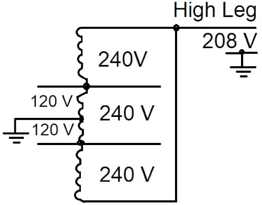
Figure 10. 120/240 V, 3-phase, 4-wire, delta system.
This scheme simultaneously supplies 120/240 V, 3-wire, single-phase; 240 V, 2-wire, single-phase; and 240 V, 3-phase power. Running wires from any two of the three wires – not including the grounded wire – supply power at 240 V, 2-wire, single-phase, and running wires from the three wires – again, not including the grounded wire – supply power at 240 V, 3-phase.
Typically, the tapped transformer has a higher kVA rating to allow for the extra power delivered to the 120/240 V, 3-wire, single-phase circuit.
The voltage between the “High Leg” and the ground is 208 V. This phase of the delta has a higher phase-to-ground voltage. The “High Leg” requires identification to avoid unintended connections of 120 V loads.
The maximum recommended voltage for this system is 240 V.
2.6 Open-delta.
Another interesting connection is the 3-phase, 4-wire, open-delta. This scheme is the delta connection of figure 8, but with two transformers.
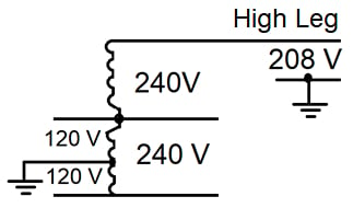
Figure 11. 120/240 V, 3-phase, 4-wire, open-delta system.
This scheme may be intentional or unplanned. If one of the transformers in the bank fails, the open-delta supplies 58% of the power available from all three transformers but keeps the load running until the replacement of the failed transformer.
By tapping one of the transformers of the open-delta at the midpoint, the scheme supplies 120/240 V, 3-wire, single-phase. See figure 11.
Conductor identification
The NEC contains several specific rules to identify conductors. The following paragraphs will show the most common methods used in daily practice to identify a single conductor.
1. Grounded conductor
a. Sizes 6 AWG or smaller: a continuous white or gray outer finish.
b. Sizes 4 AWG or larger: a white or gray marking to the insulation at all termination points when fitted.
All conductor sizes may employ three continuous white or gray stripes.
Mark the grounded conductors of various systems (unlike voltages) differently when they share enclosures – e.g., system A white and system B grey. According to the NEC, “The means of identification shall be documented in a manner that is readily available or shall be permanently posted where the conductors of different systems originate.”
The NEC does not require the typical industry practice of using gray for higher-voltage systems and white for lower-voltage systems, but it does not prohibit it either.
When different systems do not share enclosures, the grounded conductors may have the same color.
2. Ungrounded or hot conductor
a. The building has one nominal voltage system – e.g., 208 Y/120 V or 480 Y/277 V: all ungrounded conductors may be of the same color – black, red, and any combination. But never white, grey, or green.
b. The building has two or more nominal systems (whether or not they share an enclosure) – e.g., 208 Y/120 V and 480 Y/277 V: each ungrounded conductor of each system must have separate identification.
The typical identification method is color coding. Other types of marking or coding are suitable, like “marking tape, tagging, or other approved means.”
The ungrounded conductors 6 AWG and smaller – in contrast to grounded conductors – do not need identification over their entire length but “at all termination, connection, and splice points.”
The NEC requires posting the conductor identification in a readily available document or at each branch-circuit panelboard or similar distribution equipment.
Table 1 shows an example of a label identifying the conductors when two nominal voltage systems share an enclosure.
|
208 Y/120 V |
480 Y/277 V |
||
|
Phase A |
Black |
Phase A |
Brown |
|
Phase B |
Red |
Phase B |
Orange |
|
Phase C |
Blue |
Phase C |
Yellow |
|
Neutral |
White |
Neutral |
Grey |
Table 1. Conductor identification label.
3. Equipment grounding conductor
The equipment grounding conductor may be bare, covered, or insulated. When covered or insulated, it must have a continuous green outer finish or green with one or more yellow stripes.
About Branch Circuits
A branch circuit is the means to carry electric power from the final overcurrent device protecting the circuit to the outlets and equipment in residential, commercial, and industrial locations.
NEC Article 210 covers general requirements for branch circuits. Although NEC Table 210.3 “Specific-Purpose Branch Circuits” lists references for specific equipment, Article 210 always applies, with some amendments or supplements.
NEC defines four types of branch circuits.
A few typical low-voltage system arrangements supply power to the branch circuits.
The NEC rules the identification of conductors.