Facebook
 Google
 GitHub
 Linkedin
National Electrical Code 2023 Basics: Overvoltage Protection Part 2
Learn about the overvoltage protection requirements in the NEC 2023.
The most effective way of protecting all types of electric and electronic equipment is installing overvoltage protective devices at the service entrance or any power source, in-between panels, and at the point of use of the equipment. The NEC 2023 gives rules to protect the people and facilities.

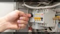
Image used courtesy of Pixabay
NEC Definition of Surge-Protective Devices (SPDs)
SPDs are devices for limiting transient voltages by diverting or limiting surge currents.
SPDs prevent the follow-on current and are capable of repeating their functions.
NEC Article 242. Overvoltage Protection
Article 242 provides the general requirements, installation requirements, and connection requirements for overvoltage protection and overvoltage protective devices.
Part II covers surge-protective devices permanently installed on premises wiring systems of not more than 1 kV, nominal.
Part III covers surge arresters permanently installed on premises wiring systems over 1 kV, nominal.
Part II of Article 242. SPDs
Section 242.6. Listing
SPDs must be listed.
Definition of listed: Equipment, materials, or services included in a list published by an organization that is acceptable to the authority having jurisdiction and concerned with evaluating products or services.
Section 242.8. Short-circuit Current Rating (SCCR)
The SPD shall be marked with a short-circuit current rating and shall not be installed at a point on the system where the available fault current is over that rating. This marking requirement shall not apply to receptacles.
When an SPD fails short-circuited, it draws the fault current. The SPD must have the capability to withstand the fault current while the overcurrent protective device clears the fault.
Section 242.12. Uses Not Permitted for SPDs
SPDs shall not be installed in:
- Circuits over 1 kV.
Ungrounded systems, impedance grounded systems, or corner grounded delta systems unless explicitly listed for use on these systems.
- Typically, manufacturers offer listed SPDs to be mounted on ungrounded systems, impedance grounded systems, and corner grounded systems.
- Where the rating of the SPD is less than the maximum continuous phase-to-ground voltage at the power frequency available at the point of application.
Remember that the normal operating voltage may be slightly higher than the rated voltage. A sustained overvoltage is not transient and may be the origin of SPD failures.
SPD Designations
There are four types of devices defined by the NEC and UL 1449 (Standard for Safety for Surge Protective Devices):
- Type 1: Permanently connected SPDs intended for installation between the secondary of the service transformer and the line side of the service disconnect overcurrent device.
Section 242.13(A)(1) authorizes its connection to the supply side of the service disconnect as permitted in 230.82(4).
According to Section 242.13(A)(2), Type 1 SPDs may also be connected like type 2 SPDs.
They may be dual-rated for Type 2 applications, providing the highest ratings available for the service equipment.
According to Section 242.13(B), when installed at services shall be connected to one of the following:
○ Grounded service conductor.
○ Grounding electrode conductor.
○ Grounding electrode for the service.
○ Equipment grounding terminal in the service equipment.
Due to their robustness and location on the power grid, Type 1 SPDs are the first line of defense against transients.
Despite being upstream of the service equipment overcurrent protection, they do not require additional external overcurrent protective devices.
In testing (Nominal discharge current): 15 x 20 kA or 10 kA, 8x20 µs surges.
- Type 2. Permanently connected SPDs intended for installation on the load side of the service disconnect overcurrent device, including SPDs located at the branch panel.
According to NEC Section 242.14, a Type 2 SPD shall be connected to:
○ Anywhere on the load side of a service disconnect overcurrent device in a service-supplied building or structure.
○ Anywhere on the load side of the first overcurrent device in a feeder-supplied building or structure.
○ On the load side of the first overcurrent device in a separately derived system.
Type 2 SPDs cannot be connected to the supply side of a service disconnect overcurrent device. However, Section 230.82(8) permits the connection of a Type 2 SPD on the supply side of the service disconnect if it is part of listed equipment and adequate overcurrent protection and disconnect means are provided.
Type 2 SPDs protect branch circuits and equipment against residual transient surges from external sources and transients from internal sources. These devices are the second line of defense against transients.
In testing (Nominal discharge current): 15 x 20 kA, 10 kA, 5 kA or 3 kA, 8x20 µs surges.
- Type 3. Point of utilization SPDs. According to Section 242.16, they shall be permitted to be installed on the load side of the branch-circuit overcurrent protection up to the equipment served – a receptacle, for example.
If included in the manufacturer’s instructions, the connection shall be a minimum of 10 m of conductor distance from the service or separately derived system disconnect.
They are the third line of defense, protecting against low-level transients from internal sources that can damage electronic circuits and electric appliances.
In testing (Nominal discharge current): 15 x 3 kA, 8x20 µs surges, or none.

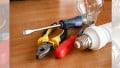
Point-of-use surge strip (Type 3). Image used courtesy of Intermatic
- Type 4 and Other Component Type SPDs. According to Section 242.18, they shall be installed by the equipment manufacturer only.
In testing (Nominal discharge current testing): like Types 1, 2, or 3 depending on the intended use.
These devices habitually are contained in listed end-use products if they meet all the conditions of adequacy and are not permitted as stand-alone SPDs.
Figure 2 shows the permitted locations for SPDs.

Figure 2. SPD locations. Image used courtesy of Lorenzo Mari
The service disconnect should always have an SPD. Depending on the installation, it is opportune to install additional SPDs in the subpanels and equipment in cascade mode. These additional SPDs are especially convenient in extensive facilities where the critical loads may be distant from the main panel.
Section 242.22. Location
This section permits placing the SPDs indoors or outdoors as long as they are unreachable to unqualified persons – unless listed for installation in accessible locations.
Section 242.24. Routing of Connections
The conductors connecting the SPDs to the line or bus and the ground shall not be any longer than necessary and shall avoid unnecessary bends.
Leads should be as short as possible. High-frequency currents, such as those typical of lightning, reduce the effectiveness of a conductor connecting the device to line and ground.
Short conductors with few bends – no sharp bends or kinks – will have a low impedance to transients. A high impedance increases the clamping voltage and reduces the protection provided by the SPDs.
SPDs connected close to the equipment achieve maximum protection. Typical figures show an increase in clamping voltage from 330 V to 560 V per meter of conductor.
Other good practices include avoiding wire nuts and canceling the magnetic fields by bundling and tie-wrapping the conductors.
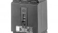
Figure 3 shows two types of SPDs appropriate for service-entrance installation – external and integrated.

Figure 3. External and integrated SPDs. Image used courtesy of Lorenzo Mari
Integrated SPDs have the advantage of reduced lead length, among others.
Section 242.28. Conductor Size
The minimum conductor size for the line and grounding conductors shall be N° 14 AWG copper or N° 12 AWG aluminum.
Section 242.30. Connection Between Conductors
This section permits connecting the SPDs between any two conductors.
The modes of protection – ways to connect the SPDs – refers to the transient paths.
There are four single modes of protection:
- Line to Line (L-L).
- Line to Neutral (L-N)
- Line to Ground (L-G)
- Neutral to Ground (N-G)
There are also multi-mode SPDs, with several components in one package, providing diverse protection modes.
This section also permits connecting the grounded conductor and the equipment grounding conductor during the regular operation of the SPD thru a surge.
NEC Definition of Surge Arrester
Surge Arresters are protective devices for limiting surge voltages by discharging or bypassing surge current. Surge Arresters also prevent the follow-on current while remaining capable of repeating their functions.
Differences between SPDs and Surge Arresters
SPDs are different from Surge Arresters. Surge arresters are used primarily on transmission lines, distribution lines, substations, and on the supply side of the service disconnect overcurrent protection.
The design of surge arresters protects electrical transmission and distribution systems from the effects of lightning, not semiconductor equipment.
SPDs reduce transient voltages to a magnitude manageable to the building’s power distribution system and the equipment, protecting semiconductor devices.
Part III of Article 242. Surge Arresters
The boundary between the SPDs covered in Part II and the Surge Arresters covered in Part III is the voltage rating of the supply system.
Some sections in Part II and Part III are similar.
- Sections 242.22 and 242.46 Location.
- Sections 242.24 and 242.48 Routing.
- Sections 242.13(B) and 242.50 Connection.
- Sections 242.32 and 242.56 Grounding electrode conductor connections and enclosures.
- Sections 242.12(3) and 242.40 Uses not permitted.
Section 242.42. Surge Arrester Rating
The duty cycle rating shall not be less than 125% of the maximum continuous operating voltage available at the point of application.
The maximum continuous operating voltage is measured from phase to ground for solidly grounded systems.
The maximum continuous operating voltage is measured from phase to phase for impedance grounded and ungrounded systems.
Section 242.44. Number Required
This section requires a surge arrester connected to each ungrounded conductor.
Section 242.52. Surge Arrester Conductors
This section requires a conductor size not smaller than N° 6 AWG, copper, or aluminum.
Key Takeaways of Overvoltage Protection
- The NEC 2023 Article 242 rules the installation and connection of overvoltage protection and overvoltage protective devices.
- Article 242 key points are:
○ Sections 242.12(3) and 242.40 Uses not permitted.
○ Section 242.6 Listing.
○ Section 242.8 Short-circuit rating.
○ Sections 242.24 and 242.48 Routing.
Featured image used courtesy of Adobe Stock