Facebook
 Google
 GitHub
 Linkedin
Substation Components—Part 3: Circuit Breakers
This article explores the crucial role of circuit breakers in substations, covering their fundamental functions, interruption processes, and the impact of transient recovery voltage (TRV) on system stability.
Circuit breakers perform two fundamental roles in substations: (1) interrupt high fault currents safely to protect equipment and limit system disturbance, and (2) provide a means of making and routing power during normal operation (switching, sectionalizing).
Their selection, topology, and ratings are central to protection coordination, system stability, and insulation coordination because interruption behavior directly determines transient voltages, energy dissipation paths, and mechanical/thermal stress on downstream equipment.
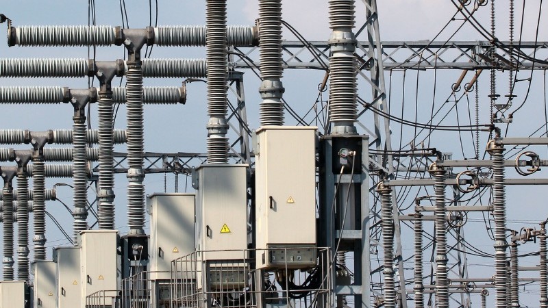
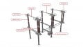
Figure 1. AC circuit breaker. Image used courtesy of ENTSO-E.
Interruption Process—Stages and Electrical/Physical Sequence
When a breaker opens under load or fault, the following sequence occurs (useful for modeling and protection design):
- Contact separation and arc initiation. As the contacts separate, a plasma arc forms between them; this arc initially conducts the current while the contacts move. Arc voltage appears across the separation and typically rises as contact spacing increases.
- Arc column evolution and energy dissipation. The arc column temperature, column conductance and surrounding medium (gas, vacuum, oil, air) determine how the arc voltage evolves and how much energy is absorbed locally versus returned to the system.
- Current decay to natural zero (AC) or forced interruption (DC). For AC circuits, the current crosses zero every half cycle — interruption is normally targeted near a current zero. For DC or high-DC-offset cases, interruption must be achieved by other mechanisms (such as commutation circuits, forced current transfer).
- Dielectric recovery and withstand after current zero. After the current reaches zero, the gap must recover dielectric strength quickly enough that the transient voltage appearing across the open contacts (the Transient Recovery Voltage, TRV) does not cause a restrike or reignition. The TRV’s amplitude and rate-of-rise are often decisive for interruption success.
Key design and modeling tasks for protection engineers, therefore, are to predict arc behavior (energy, conductance time-profile), TRV waveform and rate-of-rise, and the interaction with system impedances so that relays, breaker mechanics, and arrester coordination are correct.
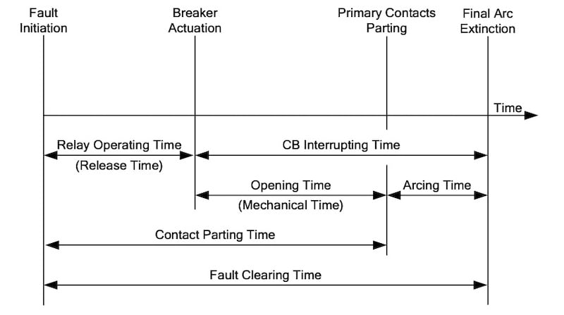
Figure 2. Circuit breaker fault clearance sequence. Image used courtesy of Schweitzer Engineering Laboratories (SEL).
Transient Recovery Voltage (TRV —What It is and Why It Matters
TRV is the voltage that appears across breaker terminals immediately after interruption and during the short transient interval before the network settles to power-frequency values. TRV is a function of system topology (line/cable capacitance, source impedance), fault type, and the sequence of pole clearances; its peak and steepness (dV/dt) govern whether the open gap withstands or a restrike occurs. TRV waveforms are standardized for type-tests and are a major factor in IEC/IEEE breaker standards and type testing (IEEE C37.011 / IEC 62271). Designing for worst-case TRV (first-pole-to-clear conditions, high capacitance networks) is critical in EHV/UHV systems.
Arc Extinction Media and Mechanisms
SF₆ circuit-breakers
- SF₆ is a high-dielectric, electronegative gas that both cools and chemically suppresses the arc by electron attachment; it allows compact interrupting chambers and high dielectric recovery after current zero. Modern SF₆ breakers use puffer or self-blast techniques to increase the gas flow through the arc. SF₆ lends excellent dielectric recovery but has environmental/regulatory constraints (GWP).
Vacuum interrupters
- In vacuum interrupters, the arc occurs in a sealed vacuum gap; the arc is primarily metal-vapor dominated and extinguishes rapidly at current zero because there is no gaseous ionization to sustain conduction. Vacuum devices have extremely fast dielectric recovery and very low continuous maintenance, but they can exhibit current-chopping (small residual current extinguished earlier than natural zero,) which can cause fast transient overvoltages; modern designs limit chopping to acceptable levels.
Oil circuit breakers
- Oil provides arc cooling and deionization; the arc vaporizes oil, producing gases and bubbles that contribute to quenching. Oil breakers were historically common but require more maintenance and have slower dielectric recovery than SF₆ or vacuum.
Air-blast and compressed-air breakers
- Use high-velocity air to cool and lengthen the arc; still used in some high-power applications but have largely been superseded by SF₆ and vacuum technologies in many networks.
Each medium implies different design tradeoffs (size, TRV tolerance, environmental & maintenance costs, life-cycle O&M). Select the medium to match system voltage, short-circuit level and TRV severity.
| Breaker Type | Arc Medium | Typical Voltage Range | Pros | Cons |
| Oil (OCB) | Mineral oil | Up to ~245 kV | Simple, effective | Fire hazard, bulky, high maintenance |
| Air-Blast | Compressed air | Up to ~765 kV | Fast, multiple operations | Noisy, large compressors, obsolete |
| SF₆ | SF₆ gas | 72.5 kV – 1100 kV | Compact, high capacity, reliable | SF₆ environmental concerns |
| Vacuum | Vacuum | Up to ~72.5 kV (developing up to 145 kV) | Long life, low maintenance, compact | Limited at very high voltages |
Table 1. Comparison of circuit breaker types
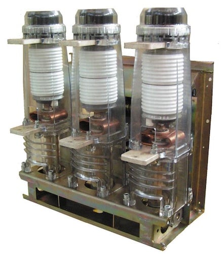
Figure 3. Three-phase vacuum circuit breaker with three vacuum interrupter housings. Image used courtesy of Wikipedia.
Key Ratings and What They Mean
Circuit breaker electrical ratings are expressed in multiple ways; the most common are:
- Rated breaking current (kA) — typically a symmetrical RMS value the breaker is type-tested to interrupt. This is often expressed also as a three-phase short-circuit MVA using:
$$\text{Short-circuit MVA (3-phase)} = \sqrt{3} V_{LL} I_{break}$$
where VLL is line-to-line voltage in kV and Ibreak is breaking current in kA; the product is reported in MVA (kV·kA→MVA). This convention is widely used in specifying substation equipment and relay settings.
- Asymmetrical (peak) rating—real faults often contain a DC offset; asymmetrical peak equals the sum of the AC peak plus DC offset contribution. Standards and manufacturers publish asymmetrical capability (often a % or a peak value) tied to a reference X/R or relay operating time.
- Making capacity (kA peak)—the maximum peak current the breaker can close onto without being damaged (important for reclosing onto faulted lines). Making capacity is usually higher than steady breaking RMS capability because the making current includes a DC offset, which results in a peak value that can be approximately 2.55 times the symmetrical breaking current. This higher peak current imposes greater mechanical and thermal stress on the breaker's contacts and components.
- Short-time withstand (kA for t seconds)—thermal endurance of busbars and breakers for a short duration (such as 1 s, 3 s) without damage; used for coordination with protection clearing times.
Example
Consider a circuit breaker rated for 40 kA interrupting current at a system voltage of 400 kV (line-to-line).
The short-circuit breaking capacity in MVA is calculated as:
$$\text{Breaking Capacity MVA} = \sqrt{3} V I$$
$$\text{Breaking Capacity MVA} = \sqrt{3} \times (400 \text{ kV}) \times (40 \text{ kA}) = 27,712.8 \text{ MVA}$$
This very large value illustrates why, in practice, system short-circuit strength is usually specified as fault current in kA at the system’s rated voltage (such as 40 kA at 400 kV) rather than expressing it in terms of the equivalent MVA.
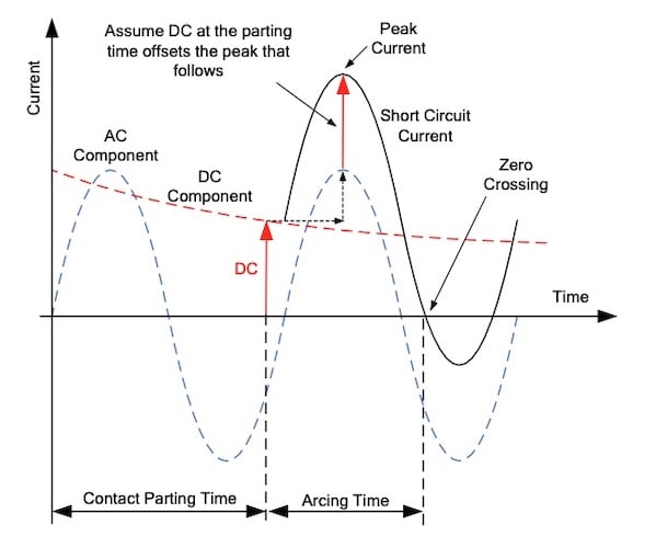
Figure 4. DC component increases the peak current value prior to zero crossing. Image used courtesy of Schweitzer Engineering Laboratories (SEL).
Contact Design and Mechanical Considerations
Contacts are made of composite materials (such as copper alloys with arc-resistant coatings) chosen for low erosion, good thermal conductivity and cathode/anode behavior under arc plasma. Contact geometry, contact travel speed and mechanism energy storage affect arcing time and thus arc energy.
Mechanical life (number of operations without major service) and electrical life (number of breaking operations at rated current) are specified separately; manufacturers provide duty curves for different operation categories. Robust mechanisms and maintenance practices are essential because contact wear changes contact timing and arc behavior (affects TRV and energy distribution).
Unwanted Transient Phenomena
- Current Chopping: particularly with vacuum interrupters, a small residual current may be interrupted before the natural current zero; the abrupt interruption of a small current can excite fast system oscillations and cause a transient overvoltage. Manufacturers design contacts and shields to limit chopping, and system protection / arrester coordination account for residual overvoltages.
- Restrike / Reignition: if the dielectric recovery after current zero is insufficient for the TRV applied, the arc can re-ignite, giving multiple arc events and large transient currents—this is a key reason why arrester placement and TRV capability are tightly coordinated in HV substations.
Protection Coordination and Operational Practice
Breaker selection must be coordinated with relay settings (operating time), cable/line/capacitor bank TRV characteristics, transformer inrush behavior and arrester ratings. Important practical points:
- First-pole-to-clear conditions produce the most severe TRV; testing and type-rating consider this scenario.
- Pole simultaneity and mechanical timing: asynchronous pole operations (delays among poles) change the TRV profile; manufacturers specify acceptable timing tolerances.
- Arrester coordination and lead inductance: short, low-inductance connections between arrester and protected object reduce transient overshoots: \( V_L = L(di/dt) \). This is why arrester placement is physically close to the equipment terminals, especially in EHV.
Key Takeaways
The role of circuit breakers in substations is crucial for maintaining the integrity and stability of power systems. By safely interrupting fault currents and facilitating safe switching operations, circuit breakers protect both equipment and the broader electrical network. Understanding the complex behaviors during interruption processes, such as arc dynamics, transient recovery voltage characteristics, and the implications of different interruption media, is vital for effective protection coordination.
The careful selection of circuit breaker types—be it SF₆, vacuum, oil, or air-blast—along with a thorough understanding of their ratings and operational mechanics, informs the design and implementation of reliable energy systems.