Facebook
 Google
 GitHub
 Linkedin
National Electrical Code Basics: Overcurrent Protection Part 2
Every electric circuit must have overcurrent protection. In Part 2, Learn about the protection of conductors, flexible cords, flexible cables, and fixture wires.
To catch up on Lorenzo Mari's series on Overcurrent Protection, please visit:
Every electric circuit must have overcurrent protection, whether a high-voltage transmission line carries many amperes or a low-voltage lighting circuit passes a few amperes. Some devices must protect conductors and equipment from overloads and short-circuits.

Image used courtesy of Pixabay
Protection of Conductors
According to NEC Section 240.4, conductors other than flexible cords, flexible cables, and fixture wires shall be protected according to the ampacities specified in Section 310.14, “Ampacities for Conductors Rated 0 V – 2 000 V.”
There are some permissions or requirements – conductors not protected in concordance with their ampacities – as follows
• Section 240.4(A). Conductors, such as fire pumps, do not require overload protection when the circuit interruption may create a hazard.
• In particular situations, you can use a fuse or a circuit breaker with an ampere rating larger than the conductor’s current-carrying capacity. Section 240.4(B) permits using the next standard overcurrent device rating above the conductor ampacity, if
◦ the conductor does not supply more than one receptacle for cord-and-plug-connected portable loads
◦ the conductor ampacity does not correspond with a standard ampere rating of a fuse or circuit breaker, and
◦ the rating selected is 800 A or less
Example 1. The allowable current rating of a busway is 47 A. Because 47 A is not a standard ampere rating, use a 50 A overcurrent protective device – the next higher standard. See Section 368.17(A) Exception N° 1.
Example 2. A cablebus rated at 94 A may use a 100 A overcurrent protective device – the next higher standard – because 94 A is not a standard ampere rating. See Section 370.23.
Section 240.4 (B) does not apply after derating a conductor – set the overcurrent device to the next lower standard – nor does it pertain to feeder taps (Section 240.21(B)) or transformer secondary conductors (Section 240.21(C)).
• Section 240.4 (C). For overcurrent devices over 800 A, the ampacity of the conductors must be equal to or higher than the overcurrent device rating.
Example 3. Compute the maximum rating of the overcurrent protective device for a feeder consisting of three 700 kcmil conductors per phase.
NEC Table 310.16 shows an ampacity of 460 A under the 75° C column.
3 x 460 A = 1 380 A
Because 1 380 A is not a standard ampere rating and exceeds 800 A, use a 1 200 A overcurrent protective device – the next lower standard.
• Section 240.4(D) establishes limitations in the overcurrent protection of small conductor sizes. Table 1 shows the maximum overcurrent protective device ampere ratings after applying any correction factors for ambient temperature and number of conductors. See asterisk in notes to NEC Table 310.16.
|
Size AWG |
Maximum overcurrent protection (A) |
|
18 (only Cu) |
7 |
|
16 (only Cu) |
10 |
|
14 (only Cu) |
15 |
|
12 (Al and Cu-clad Al) |
15 |
|
12 (Cu) |
20 |
|
10 (Al and Cu-clad Al) |
25 |
|
10 (Cu) |
30 |
Table 1. Maximum overcurrent protection of small conductors.
Example 4. What’s the maximum allowed fuse size to protect a No. 14 AWG THW conductor?
Table 1 shows 15 A
• Section 240.4(E) lists the NEC sections concerned with the protection of tap conductors.
•Section 240.4(F). Single-phase transformers with 2-wire primary circuits and 2-wire secondaries, and 3-phase, delta-delta connected transformers with a 3-wire secondary, may have the secondary circuit conductors protected by the primary circuit overcurrent device if the transformers voltage ratio is the basis to compute the size of conductors and rating of the protective devices.
The primary circuit overcurrent device does not protect the secondary conductors in all other transformer connections.
Example 5.
Figure 1 shows a single-phase 2-wire transformer and circuit conductors supplying a panel
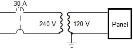
Figure 1. 2-wire transformer circuit. Image used courtesy of Lorenzo Mari
a. Compute the maximum current in the primary circuit to accept the 30 A circuit breaker as the transformer protection.
NEC Table 450.3(B) sets the protective device at 125% of the rated primary current for primary-only protection.
30 A = 125% x primary current
Primary current = 30 A/1.25 = 24 A
b. Compute the primary circuit minimum-size copper conductor.
Table 1 shows that a 30 A device protects a conductor size N° 10 AWG. This protection is adequate for continuous and non-continuous loads.
c. Compute the secondary circuit minimum-size copper conductor.
Secondary current = 24 A x 240 V/120 V = 48 A
NEC Table 310.16 shows a conductor size N° 6 AWG TW with 55 A ampacity.
d. Confirm that the primary protection protects the secondary conductor.
55 A x 120 V/240 V = 27.5 A. 30 A > 27.5 A Does not comply with 240.4(F).
Try with conductor size N° 4 AWG TW. NEC Table 310.16 shows an ampacity of 70 A.
70 A x 120 V/240 V = 35 A. 30 A < 35 A. Complies with 240.4(F)
The secondary circuit minimum-size copper conductor is N° 4 AWG TW
e. Find a quicker way to answer questions c and d simultaneously.
30 A x 240 V/120 V = 60 A
NEC Table 310.16 shows an ampacity of 70 A for conductor size N° 4 AWG TW.
70 A x 120 V/240 V = 35 A. 30 A < 35 A. Complies with 240.4(F)
Example 6.
The power of the transformer in example 5 is 24 A x 240 V = 5.76 kVA – a non-standard rating. Assume a standard 5 kVA single-phase sealed transformer for the hookup of figure 1.
A. Compute the rated primary current
5 kVA/240 V = 20.83 A
B. Compute the maximum rating of the overcurrent device to protect the transformer
125% x 20.83 A = 26 A
Note 1 to NEC Table 450.3 (B) permits the next higher standard rating of protective device. Use 30 A.
Compute the minimum-size primary and secondary copper conductors.
From example 5, use N° 10 AWG TW for the primary circuit and N° 4 AWG TW for the secondary circuit.
• NEC Table 240.4(G) lists section numbers for the overcurrent protection of specific conductors.
Protection of Flexible Cords, Flexible Cables, and Fixture Wires
• NEC Tables 400.5(A)(1) and 400.5(A)(2) show the ampacities for the protection of standard flexible cords and flexible cables. These tables comprise all types described in Table 400.4, including tinsel cord (TPT and TST).
• Section 240.5(B)(1) states that the branch circuit overcurrent protection device will protect a flexible cord used to supply listed appliances or luminaires when used in compliance with their listing requirements.
• Section 240.5(B)(2) permits tapping the fixture wire to the branch circuit conductors per table 2.
|
Branch-circuit rating (A) |
Minimum wire size (AWG) |
Restrictions |
|
15 |
18 |
Up to 15 m length |
|
20 |
18 |
Up to 15 m length |
|
15 |
16 |
Up to 30 m length |
|
20 |
16 |
Up to 30 m length |
|
20 |
14 |
- |
|
30 |
14 |
- |
|
40 |
12 |
- |
|
50 |
12 |
- |
Table 2. Minimum fixture wire size for tapping branch circuit conductors.
• NEC Table 402.5 shows the ampacities for the protection of fixture wire for all types listed in Table 402.3.
• The supplementary protection, covered in Section 240.10, is valid to protect flexible cords, flexible cables, and fixture wires.
• Section 240.5(B)(3) indicates that the branch circuit overcurrent protection device will protect listed extension cord sets when used in compliance with their listing requirements.
• According to Section 240.5(B)(4), a 20 A branch circuit protects a field assembled extension cord set when made with wire size 16 AWG or larger.
• Section 240.8. Fuses and circuit breakers may be paralleled if factory assembled in parallel, tested, and listed as a single unit.
• Section 240.9 permits thermal devices to protect motor branch-circuit conductors from overload. Protect the thermal devices according to Section 430.40.
• Section 240.10 does not permit supplementary overcurrent protection as a substitute for the required branch-circuit overcurrent devices. Therefore, supplementary overcurrent protection need not be readily accessible.
• It is vital to selectively coordinate the overcurrent protection system to minimize the hazard to personnel and equipment. Section 240.12 permits such protective system coordination.
By selectively coordinating the protection system, only the closest overcurrent protective device to the fault operates. The upstream protective devices remain closed, and the rest of the electric system continues to energize – preventing a blackout or extensive shutdown.
An overload condition may activate an alarm instead of the automatic opening of a protective device. This alarm will allow the operator to resolve the problem, keep the system on, or start a predetermined shutdown procedure.
• Section 230.95 requires ground-fault protection on specific electrical equipment. Section 240.13 requires ground-fault protection of equipment (GFPE), according to Section 230.95, for all 3-phase, 4-wire, 277Y/480 V devices – rated above 1 000 A – used as main disconnecting means in buildings or structures. GFPEs protect equipment and NOT people.
This requirement does not apply to a continuous industrial process where a nonorderly shutdown will introduce or increase hazards.
A ground-fault protective device consists of a ground-fault sensor (toroid) encircling the phases and the neutral conductor. The device also has a relay to control the overcurrent protective device.
The relay receives no signal as long as the phasor sum of the currents in the enclosed conductors is zero – all currents remain inside the sensor.
When a ground fault occurs, the fault current returns to the source through random paths outside the sensor, and the phasor sum is not zero anymore. The sensor sends a signal to the relay. If the current unbalance reaches a preset value for a preset time, the relay trips the protective device – usually circuit breaker.
• Section 240.15(A) requires a fuse or an overcurrent trip unit of a circuit breaker connected in series with each ungrounded conductor – they will open or trip under overload or ground fault conditions, clearing the fault.
A current transformer and an overcurrent relay are equivalent to an overcurrent trip unit.
• Section 240.15(B). Circuit breakers must open all ungrounded conductors simultaneously, automatically, or manually as a disconnecting means.
Example 7. A 3-pole circuit breaker protects a 3-wire circuit. If one of the three wires develops a fault, the circuit breaker must open all three wires simultaneously, not just the faulted one. It will also open the three phases when manually driven.
• Section 240.15(B)(1). Single-pole circuit breakers may protect multiwire branch circuits serving only line-to-neutral loads. Join the handles of the circuit breakers by identified handle ties – not wires, nails, or other non-identified objects, which are unacceptable.
• Section 240.15(B)(2) permits 120/240 V rated single-pole circuit breakers with identified handle ties to protect ungrounded conductors for line-to-line connected loads in grounded single-phase systems. See figures 2 and 3.
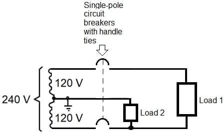
Figure 2. Single-phase, 3-wire, 120/240 V branch circuit.
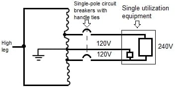
Figure 3. Single-phase, 3-wire, 120/240 V branch circuit from 3-phase, 4-wire delta system. Image used courtesy of Lorenzo Mari
• Section 240.15(B)(3) permits using 120/240 V rated single-pole circuit breakers with identified handle ties to protect ungrounded conductors in grounded 4-wire, 3-phase systems, and 5-wire, 2-phase systems. The voltage to the ground cannot exceed 120 V. See figure 4.
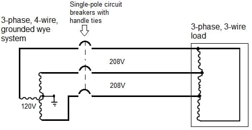
Figure 4. 3-phase, 208 V branch circuit, from 3-phase, 4-wire, grounded wye system. Image used courtesy of Lorenzo Mari
• Section 240.15(B)(4) permits using single-pole, 125/250 V DC-rated circuit breakers with identified handle ties to protect ungrounded conductors for line-to-line connected loads in 3-wire systems supplied from a system with a grounded neutral. The voltage to the ground cannot exceed 125 V.
Note that sections 240.15(B)(1) to B(4) require grounded neutrals to permit the use of single-pole circuit breakers joined by identified handle ties.
Branch circuits not complying with the conditions set forth from B(1) through B(4) require multipole common trip circuit breakers. Figures 5 and 6 show ungrounded systems requiring multipole circuit breakers.
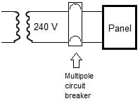
Figure 5. 2-wire ungrounded branch circuit. Image used courtesy of Lorenzo Mari
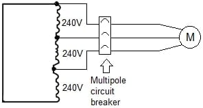
Figure 6. 3-phase, 3-wire, ungrounded branch circuit. Image used courtesy of Lorenzo Mari
Key Takeaways
- NEC Section 240.4 gives rules to protect the conductors.
- Section 240.5 deals with the protection of flexible cords, flexible cables, and fixture wires.
- Section 240.8 permits fuses and circuit breakers in parallel if factory assembled.
- Section 240.9 prohibits using thermal devices to protect against short-circuits and ground faults.
- Section 240.10 prohibits using supplementary overcurrent protection as a substitute for the required branch-circuit overcurrent devices.
- Section 240.12 permits the coordination of the overcurrent devices.
- Section 240.13 requires GFPE in solidly grounded wye electrical systems with more than 150 V to the ground and less than 1 000 A.
- Section 240.15 has requirements regarding the overcurrent devices in the ungrounded conductors.
Featured image used courtesy of Pixabay