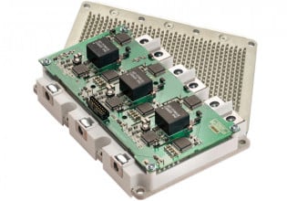
Module Solutions for 1500V Solar Inverters
This article discusses the feasibility of increasing the maximum DC voltage of solar inverter to make solar power plants more cost-effective.
By increasing the maximum DC Voltage of a solar inverter from 1000V to 1500V PV power plants become more cost-effective. However, this voltage jump requires careful consideration when selecting power modules and converter topologies.
PV based power plants are relatively expensive solutions in the market of energy generation technologies. Low voltage components and cabling of the arrays are a significant part of the cost of the PV installations. Many studies have concluded that increase of the inverter voltage, and thus system voltage from 1000V to 1500V offers opportunities to reduce the initial PV array cost by reducing the number of low voltage components and the total cabling needed. The system also has the potential to be more efficient at the grid or the DC side. This aspect is already known from power systems that when voltage levels are increased, ohmic losses are decreased. Typical cost savings for 1500V PV installations are shown in Figure 1.
Figure 1: Cost comparison 1000V vs 1500V system
Implications to Power Modules
While 1500V is becoming the mainstream for solar inverters (central and string), this new voltage requires careful consideration with respect to creepage and clearance of the power modules and the DC link assembly as well. Also, the new requirement from solar inverter is to operate at near-zero power factor. This fact needs to be accounted for when selecting the modules.
Consequences on the Inverter
Increasing the system voltage from 1000V to 1500V increases the output voltage of the inverter. While the open circuit voltage is 1500V, extracting full power or Maximum Power Point (MPP) voltage range could vary from system to system and mission profile. Hence, this will impact the selection of the appropriate topologies to meet system requirements. This, in turn, influences the choice of the power modules.
Various topologies are available to address higher DC voltages. Two level topology equipped with 1700V devices is the most common and basic configuration. This is shown in Figure 2.a. Its performance and limitations are well known due two level output waveform, high filtering requirement and low efficiency.
To improve the performance of the solar installations, industry-standard three level topologies could be utilized. One solution consists in adopting transistor clamped topology, 3L-TNPC. This topology is obtained by inserting two switches in common emitter configuration between the AC terminal and the midpoint of the DC link referred as N, Figure 2.b Another option is the adoption of three level neutral point converter, 3L–NPC as shown in Figure 2.c This configuration has two additional clamping diodes that allow impressing half the DC link voltage across all the switches.
Three level topologies offer the following distinct advantages over two level topologies: i) synthesized AC output waveform has higher resolution (3L waveform), ii) duty cycles of the switches are distributed on various switches hence better heat distribution among the switches, iii) switching frequency doubling effect and iv) lower semiconductor losses. The reader is referred to Semikron’s application note [1] for a detailed overview and operation of three level converters.
Figure 2: 2-Level (left), 3-Level T-NPC (middle) and 3-Level NPC topology (right)
Topology Selection
In this section, by way of a concrete example, various topologies are compared under the same operating conditions.
Conditions are summarized as follows: Pnom=640kW, Vout =550V, cos(φ)=0.95, Vdc=900V-1200V, fsw=2-6kHz and Rth(s-a)=0.088K/W per module (air-cooled)
In this example, Semikron’s SEMiX® platform is considered.
SEMiX® platform is flexible and well suited to address numerous requirements in one housing. It is also an Industry-standard module which allows compact inverter designs. Here, two level topology implemented in a SEMiX®3 Press-fit package, Figure 3a and three level topologies (NPC or TNPC) are realized with SEMiX®5 packages, Figure 3b. Both packages are available with press-fit pins for ease of assembly and manufacturing.
Benefits of SEMiX®:
- Optimized internal chip layout and design
- Housing features rugged molded power terminals for superior mechanical stability
- Flat 17mm package, and separated AC and DC terminal for state of the art inverter design
- Gate driver mounted directly on top of the module
Figure 3a: SEMiX®3 Press-fit
Figure 3b) SEMiX®5 modules
Set-Up:
- 2L-1700V solution: 4 x SEMiX453GB17E4p
- 3L NPC-1200V solution: 4 x SEMiX305MLI12E4p
- 3L TNPC-1700V/1200V solution : 4 x SEMiX305TMLI12E4p
Figure 4 a): Efficiency comparison. 900VDC
The modules are equipped with Trench 4 medium power IGBTs (E4 type) and with Semikron’s CAL4F Diodes. Efficiencies at 900V and 1200V DC bus are shown in Figure 4a and 4b respectively. Results show that the three level topologies have lowest semiconductor losses when switching frequency is higher than 3kHz.
Figure 4 b): Efficiency comparison. 1200VDC.
Optimal Topology-Accounting for Cosmic Rays Failures
Unfortunately, calculating efficiencies of various configurations will not permit the design Engineer to decide which topology is optimum. This is due to the fact that mission profile is not accounted for and cosmic ray failures are excluded. Evaluating these aspects will lead to the optimal topology.
FIT rate caused by cosmic rays of Semikron’s 1700V CAL4 diodes and their superior robustness compared to competitor’s diodes is well documented in [2-3].
The failure rate of the inverter could be computed by considering the mission profile or in another word time share of the inverter spent at a given voltage during the day. For the above example, we will consider three different profiles. Profile 1 is lowest time share at the highest DC link voltage (1550V), Profile 2 is medium time share at the highest DC voltage, and Profile 3 has the highest time share at the highest DC voltage. These results are summarized at sea level and for 12 hours of operation per day. The comparison of various solutions, Table 1, shows that 3L-NPC has the lowest cosmic ray failures. This is thanks to the fact that the serial connection of four 1200V IGBTs the topology does not operate at the voltage limits of the module and the design margin is high.
It is worth to note that 2-level and 3L-TNPC inverters are operating with the same chip voltage. However, the lower cosmic ray failure rate of the TNPC compared to the 2-level system is based upon less 1700V chip area (66%) because the duty cycle of the 1700V chips is lower due to additional neutral current path. Further, if the altitude is above the sea level then the intensity of the cosmic rays increases and follows approximately an exponential curve. Typically, one can state that the failure rate increases by a factor of two for 1000m elevation gain. Hence, the cosmic ray failure rate of solar filed installations at high altitude is significantly higher.
| TOPOLOGY | Profile 1 | Profile 2 | Profile 3 |
| Failure rate/FIT Failures per year @12h/d | |||
| 2L-1700V Solution | 7 0.003% |
12 0.005% |
112 0.049% |
| 3L TNPC-1700V/1200V solution | 3 0.001% |
4 0.002% |
40 0.018% |
| 3L NPC-1200V solution | <1 <0.001% |
<1 <0.001% |
<1 <0.001% |
| Average Voltage | 1203 V | 1245 V | 1251 V |
Table 1: Failure rate of inverters by cosmic ray at sea level with various topologies and different mission profiles.
Based on the above study and calculations, 3L -TNPC based systems have the best efficiency, and is characterized by simple and proven inverter design and an acceptable cosmic ray failure rate and also thanks to superior cosmic ray robustness of Semikron’s CAL4F diode technology which plays an important role in further improving inverter reliability.
3L- NPC systems have high efficiency at high switching frequencies and due to the fact that cosmic ray failures can be neglected in our view is the best solution. The disadvantage of this system is a complex inverter design. However, the topology is well established in the industry and the technology is proven already. The 2-level inverter stands out due to its simple design (driver and controller) and the most cost effective solution of semiconductors (filters neglected). Disadvantages are due to its limited performances: i) lower switching frequency ii) higher cosmic ray failure rate compared to the 3-level solutions.
If the MPP range is below 1300V then 2L 1700V or 3L-TNPC 1700V/1200V solutions could be considered. On the other hand, if operating voltage exceeds 1300V then the 3L-NPC 1200V is the best choice.
In summary, the strength and weaknesses of each topology could be summarized as follows:
- 2L with 1700V IGBT has the shortest time to market and reuse of existing assemblies is possible. However, it has poor efficiency when the switching frequency exceeds 2 kHz.
- 3L NPC with 1200V IGBT has no limitations to operate up to 1500V and has excellent efficiency beyond 5 kHz switching frequency.
- 3L TNPC with 1700V/1200V IGBT is simple and has good performance at medium switching frequencies and lower DC voltages.
It follows from the discussion above that 3L-NPC 1200V should be the preferred solution from reliability point of view and when operation at higher DC voltages is required to harvest maximum energy from PV panels.
Portfolio for 1500V Solar Inverters
Semikron offers complete module portfolio for 1500V PV applications.
These modules are ready to be used in string and central inverters. Hence, a wide power range in solar installations is covered.
SEMITOP and MiniSKiiP platforms are well suited for small and medium power applications. SEMiX, SKiM and SKiiP platforms are good match for medium power converters. SEMTRANS 10 based solutions are effective for high power applications.
Innovative Approach for 3L-NPC 1200V
Semikron has recently introduced an elegant solution that overcomes the challenges associated in paralleling three level NPC inverters. This approach is suitable to build scalable and modular phase legs. Semikron’s concept takes advantage of the symmetry in the NPC topology and uses two half NPC topologies referred as MLI TOP and MLI BOT. Each half MLI topology is implemented in its own module as shown in Figure 5. Two different platforms are available to implement 3L-NPC with the new approach. The first one is the use of Semikron’s 2nd generation SEMITOP® module in E2 package and the second one is based upon SEMITRANS®10 package. Both modules are industry standard modules and are suitable for 1500V solar inverters.
Figure 5a: 3L-NPC Inverter SEMITRANS® 10 MLI concept
Figure 5b: 3L-NPC Inverter Split NPC topology
SEMITRANS 10 MLI for Central Inverters
In central inverters, the trend is for higher DC voltages by means of over paneling to increase the annual yield of energy. As already mentioned above, here the 3-L NPC topology is the best solution. For these types of inverters, Semikron introduced the SEMITRANS® 10 MLI modules where the NPC topology is split to two halves. With current rating of 1200A and the use of 1200V medium power (E4) IGBT chips in combination with Semikron CAL4F diodes SEMITRANS® 10 MLI enables air-cooled power blocks up to 750kW without paralleling of modules. Similar to Semikron’s standard SEMITRANS® 10 modules, MLI version modules utilize an advanced baseplate soldering process to create a very robust package for passive temperature cycling to increase the lifetime of the modules also in harsh environment.
Figure 5a shows SEMITRANS® 10 MLI implementation and Figure 5b highlights split NPC topology concept.
Benefits of SEMITRANS®10 MLI:
- Industry-standard module
- High power three level NPC building block without paralleling modules
- Compact, scalable and efficient design
- Advanced baseplate soldering
To demonstrate the benefits of this split topology Semikron has developed two different application samples for power stacks, using SEMTRANS® 10 MLI:
3-phase 750kW building block without paralleling of modules, Figure 6.
Figure 6: Application Sample three-phase 750kW SEMITRANS®10 MLI stack
Figure 7: Applications Sample Single Phase 1500kW SEMITRANS®10 MLI
Single phase 1.500kW building block with two parallel modules, Figure 7.
This compact solution based on two SEMITRANS® 10 MLI modules allows an easy DC-link connection and low stray inductances. About 24nH for the outer switches and 64nH for the inner switches are responsible in lowering overvoltages in the inverter.
Compared to competitor solutions using three modules with the same packaging technology like SEMITRANS® 10 MLI this brings significant benefits which are: lower losses, less space and simpler design. The efficiency can reach 98,8% @ fsw=5kHz and up to 99,0% with fsw=3kHz, and modules exhibit up to 15% lower junction temperatures when compared to competitor modules or available industry solutions.
Also, the driver effort is clearly reduced by using only two modules for the NPC topology instead of three.
For fast time to market, in addition to power modules Semikron can provide dual adapter boards for a pair of SEMITRANS® 10 MLI modules (top + bottom) including two SKYPER 42 LJ drivers. These adapter boards also include gate resistors, VCEsat monitoring circuitry for all IGBTs, active clamping and error management. SEMITRANS® 10 modules are also available with pre-applied phase change thermal interface material for optimal thermal conduction and a clean manufacturing process.
Conclusion and Summary
Solar energy growth is fueled by cost reduction. Increasing the voltage levels from 1000V to 1500V overcomes the high cost of energy generation. On the other hand, this voltage change has implications and challenges on the inverter modules and topologies that are required to build solar plants.
Semikron, a leader in power modules, offers various solutions to the PV market. Its portfolio covers the demands and the challenges of the 1500V solar inverters with innovative packaging technologies and module solutions. Semikron’s complete portfolio provides coverage from string inverters up to central inverters for installations in the MW range. Further, efficiency, power density, reliability and scalability demands are addressed with various platforms. Hence, customer cost-performance ratios and specific needs are met effectively.
In particular, recently introduced SEMITRANS® 10 MLI based solution shows significant benefits for new 1500V central inverter systems.
About the Authors
Kevork Hadda works as the Product Development Manager of SEMIKRON Elektronik GmbH & Co. KG, an Electronics company in Nuremberg, Germany. He is responsible for the Project Management Group, Engineering Group, as well as R&D and Application activities. He earned his Bachelor's Degree in Electrical Engineering with specialization in Power Electronics at Saint Joseph University (ESIB)-Beirut, Lebanon. He then acquired his Master's degree in Applied Science - Electrical Engineering specialized in Power Electronics at Concordia University, Montreal, Quebec, Canada.
Bernhard Eichler is the Product Marketing Manager of SEMIKRON Elektronik GmbH & Co. KG, Nuremberg, Germany. He owns a diploma in electrical engineering and an M.B.A. He worked as an R&D engineer and Product Manager for renewable energy converters at Siemens before he joined SEMIKRON in 2016. At SEMIKRON Bernhard is responsible for the international product marketing activities for the markets solar, wind energy and traction.
References
- I. Staudt, “AN 11001”, 2015. https://www.semikron.com/dl/servicesupport/downloads/download/semikron-a... topology-en-2015-10-12-rev-05.pdf
- U. Scheuermann, U. Schilling, “Cosmic ray failures of power modules-the diode makes the difference”, PCIM Europe 2015, Nuremberg, Germany.
- C. Felgemacher, S.V. Araujo, P. Zacharias, K. Nesemann, A. Gruber, “Cosmic radiation ruggedness of Si and SiC power semiconductors”, ISPSD June 2016, Prague, Czech Republic.
This article originally appeared in the Bodo’s Power Systems magazine.


