Facebook
 Google
 GitHub
 Linkedin
Power Module Dynamic Test Solution Suitable Also for WBG Devices
Evaluation of power modules is important for power electronics engineers, as well as power module manufacturers, to design efficient, small form factor, and reliable power converters. There are multiple challenges for these engineers to overcome when evaluating power modules, especially for power modules made with WBG devices.
Power modules typically have higher power density than discrete power devices, incorporating multiple field-effect transistor (FET) chips to increase current. High current, such as 400 A, is necessary for some EV applications where silicon carbide (SiC) devices are being used to increase voltage and reduce charging time. Therefore, high current with high bandwidth is required for WBG power module testing.
The Challenges of Power Module Dynamic Test
Most power electronics applications require half-bridge structures as the basis for inverters and converters. Depending on the application, 2-in-1, 4-in-1, or 6-in-1 configurations are used. Two-in-1 configurations are half-bridge structures, 4-in-1 configurations are typically H-bridge structures, and 6-in-1 configurations are used for 3-phase power converters. In the case of discrete power devices, such as in TO-247 packages, it is possible to evaluate an individual device by placing it at the low side in a double-pulse test (DPT) setup. However, it is necessary to perform measurements on both the low-side and the high-side device to characterize a half-bridge module, because you cannot assume the high-side device behaves exactly like the low-side device. The voltage potential at the junction between the high-side device source and low-side device drain in a half-bridge configuration dynamically changes with large voltage swings (e.g., 0 V to 600 V) as the half-bridge is switched. This makes the measurement of the high-side FET very challenging, especially for small gate voltages. Measurement of a 10 V to 20 V gate voltage, while the reference for this measurement (i.e., the source) switches up and down, hundreds of volts with fast slew rates is very difficult, unless you have high common-mode rejection (CMR) probing technology.
When measuring high-side Vgs, the industry tends to think high CMR is the only necessary parameter to make accurate measurements. However, the bandwidth and noise specifications of the probe are also critical factors for accurate measurement.
Power modules come in a variety of form factors. Emerging WBG devices drive even more variations because of their high-power density and potential to make the module more compact. When evaluating power modules, the associated PC board layout needs to be carefully designed. Double-pulse test (DPT) boards typically integrate almost all DPT components, such as the connection to the power module, gate drivers, decoupling capacitors, and current measurement. The power module is often soldered to the test board to minimize the stray inductance. However, the need to solder and unsolder multiple power modules makes the evaluation of the power module time-consuming and inefficient.
Many R&D engineers in the industry either use an older production-type dynamic power module tester for silicon (Si) power devices or a custom setup made in-house by integrating a function generator, power supply, oscilloscope, and probes with a custom made DPT board. The former solution provides DPT capability but is not suitable for detailed evaluation of faster WBG-based devices. Because these systems typically require tedious programming to set up and execute tests, the process can be inefficient and cumbersome. This makes it difficult to apply various test conditions for comprehensive analysis of the power module. The cost to purchase and maintain these production-type systems can also be excessive. The latter solution often lacks repeatable results, ease of use, safety, and correlation with the other in-house test systems. The next DPT system design is improved by creating different versions of DPT test systems, leading to inconsistent results and additional support and maintenance issues.
Providing temperature dependence measurements for the power module’s dynamic characteristics is critical as the applications often require harsh environments, such as hot deserts, humid tropical forests or extreme cold with heavy snow fall. Testing power modules in such temperature conditions using a thermostatic chamber is not easy, especially for dynamic characterization.
Extending the Dynamic Power Device Analyzer Portfolio
Introduced in 2019, Keysight’s PD1500A Power Device Dynamic Analyzer/Double-Pulse Tester has been used by many power semiconductor manufacturers and users around the world. Leveraging Keysight’s success with the PD1500A as well as measurement science knowledge and RF test expertise, enabled the company to develop a power module DPT solution with unprecedentedly clean, repeatable, and reliable waveforms and extractions. The same ‘ease of use‘ and compliance to safety regulations as the PD1500A are well accepted by power electronics engineers.
Keysight introduced a new DPT system called the PD1550A Advanced Dynamic Power Device Analyzer by expanding the PD1500A’s capabilities to test power modules. The system is valuable to automotive OEM and Tier 1 power converter designers. Understanding power module behavior and characteristics is critical to designing safe and reliable power circuits for automotive applications. Some of the key features solve the challenges for power module testing described above.

Figure 1. More than 500 A Id test results on SiC power module (FF2MR12KM1P). Image used courtesy of Bodo’s Power Systems
Current capacity is increased from 200 A to 1000 A while still using a coaxial shunt as a current sensor to maintain high bandwidth current measurements.
Depending on the current level and required accuracy, users can select and attach a 5 mΩ or a 50 mΩ coaxial shunt resistor. Each shunt is characterized to flatten the frequency response to the specified bandwidth. RF compensation data is supplied for each shunt and is applied to the raw measurement data to produce accurate results by eliminating unwanted bandwidth variation of the current shunts. Figure 1 shows example test results for Id > 500 A measured with the new PD1550A. Figure 2 shows the effectiveness of RF compensation, which makes the waveform accurate and consistent regardless of the bandwidth of the shunt resistor which is used.

Figure 2. Effect of RF compensation on drain current. Image used courtesy of Bodo’s Power Systems

Figure 3. High-side Vgs measurement results comparison. Image used courtesy of Bodo’s Power Systems
The PD1550A is capable of the following Vds, Id, and Vgs ranges, which cover a variety of power modules:
- Drain voltage (Vds): 1.36kV (force), 2kV (measure with differential probe)
- Drain current (Id): 1kA (force), 2kA (measure)
- Gate voltage (Vgs): -28V to +28V with no Under Voltage Lock Out (force)
These ranges apply to both low-side and high-side device testing.

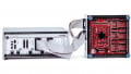
Figure 4. DUT interface board and gate resistor module. Image used courtesy of Bodo’s Power Systems
A big challenge to test gate voltage characteristics on the high-side device is solved by newly developed “true pulse isolated probe technology”. Specially designed probing, fully isolated from the other probes, allows accurate Vgs measurement for the high-side device in a half-bridge configuration power module as shown in Figure 3. It clearly shows the newly developed “true pulse isolated probe” has sufficient CMR and superior noise performance (gold waveform) compared to the commercially available optically isolated probe (blue waveform).
The PD1550A inherits its modular architecture from the PD1500A, allowing Keysight to leverage the test system software framework that provides features such as the easy-to-use user interface. By just filling in test conditions for Vds, Vgs, Id, 2nd pulse width, off time, and temperature (optional), the user is only a mouse-click away from performing fully automated tests. The user can sweep Vds, Id, and even temperature, allowing hundreds of tests to be automated, enabling lots of repeatable and reliable data for statistical analysis. Presentation of the test results has many options, such as extracted parameters, DPT waveforms, or switching locus, and gate charge graphs. The “Measurement History” function allows quick search and recall of measured data for deeper analysis, duplicating tests applying the same test condition to a different device, or troubleshooting a test setup.
An interface board that attaches to the power module is the only component required to be customized, depending on the power module’s layout. Keysight application experts can provide thorough design services to create these customized boards. An example of an interface board is shown in Figure 4. These customized boards incorporate technology that makes it easy to attach the board to the power module without soldering, which allows repeated use of the board for many DUTs, while creating a solder-like connection. The gate resistor (Rg) is an important component when characterizing the power module. A small gate resistor module is also shown in Figure 4. Each gate resistor module has an EEPROM which contains the resistor value. The PD1500A software recognizes the resistor value automatically and uses the value for testing. An EEPROM is also used on other DPT components, such as the interface board and the gate driver board, reducing the chance of operator error and further enhancing the reliability of the system.
As we previously mentioned, another critical evaluation factor is temperature dependency. The PD1550A supports two types of thermal management techniques. One is a hot plate that allows a temperature range from room temperature to 200 °C. The other technique is a ThermoStream® that can make measurements in cold ambient down to -40 °C, as well as high temperatures up to 200 °C. The thermal test equipment is automatically controlled by the system software making it simple to obtain temperature-dependent characteristics.

Figure 5. IGBT power module test result examples (25 °C & 150 °C). Image used courtesy of Bodo’s Power Systems

Image used courtesy of Bodo’s Power Systems
The Keysight PD1550A also complies with international safety regulations such as Compliance, Safety, Accountability (CSA), CE, and KCC. You will be ensured to test your device safely.
Summary
Keysight’s PD1550A Advanced Power Device Dynamic Analyzer is a newly developed DPT characterization solution for power modules. The first version provides measurement and extraction of the double pulse test parameters you are used to measuring with the PD1500A, including some additional high-side parameters.
The PD1550A will soon be enhanced to measure discrete devices as well as other reliable test applications such as short circuits and UIS. The PD1550A was designed with the same goal as the PD1500A, to provide repeatable and reliable dynamic characterization of WBG devices. Key features include larger voltage and current ranges, True Pulse Isolated Probe, RF characterization and compensation of each current sensor, interface board with solderless contacts, and easy-to-use software that will contribute to significantly improving productivity on power device and power module evaluation.
This article originally appeared in Bodo’s Power Systems magazine.