 Facebook
 Google
 GitHub
 Linkedin
Enhanced Power Module for PV and PCS/ESS Applications
In this article, we present two key module-based technologies that further improve inverter performance—robust silicon nitride (Si3N4) substrate ceramics and power devices built to operate at junction temperatures of up to 175 °C.
This article is published by EEPower as part of an exclusive digital content partnership with Bodo’s Power Systems.
Modern power conversion systems must increase power density and reduce per-kilowatt cost, yet maintain inverters’ current footprints. Several developments at the system level support these goals. Inverters can deliver more power without requiring larger conductors or modules if they can be made to operate at higher DC and AC voltages while retaining similar maximum phase currents.
Optimized switching strategies, such as discontinuous pulse width modulation (DPWM), can reduce switching losses significantly, in some cases by more than 30%, enabling more efficient operation. Mechanical and thermal improvements, including advanced heatsink structures and heat-pipe integration, extend the allowable dissipation capacity and push inverter designs closer to their theoretical performance limits.
While system-level optimizations deliver valuable gains, further increases in performance require advances within the power module itself – specifically, a transition to Si3N4 substrates and operation at junction temperatures of up to 175°C. These two improvements significantly expand what is thermally and electrically achievable within a given module’s footprint.
Si3N4 substrates have lower thermal resistance and are more rugged than conventional materials, so they improve overall thermal conductivity and mechanical robustness. They also support higher output power without requiring changes to the power module or the inverter’s mechanical envelope.
The capacity to operate at junction temperatures of up to 175°C increases thermal headroom. Higher allowable junction temperatures expand the safe operating area, provide tolerance for transient overload conditions, and extend lifetime under demanding mission profiles. The greater thermal headroom enables designers to make the most of higher voltages, improved switching strategies, and optimized thermal paths without compromising reliability.
Flow E3BP and Flow E3BP+ at a Glance
Vincotech’s flow E3BP+ module builds on the flow E3BP platform (Figure 1). This enhanced version supports junction temperatures of up to 175°C and incorporates Si3N4 ceramic substrates, while maintaining full compatibility with the compact 110mm × 62mm outline. Its Si3N4 substrates reduce thermal resistance by 26% compared with equivalent Al2O3-based DCB layouts.
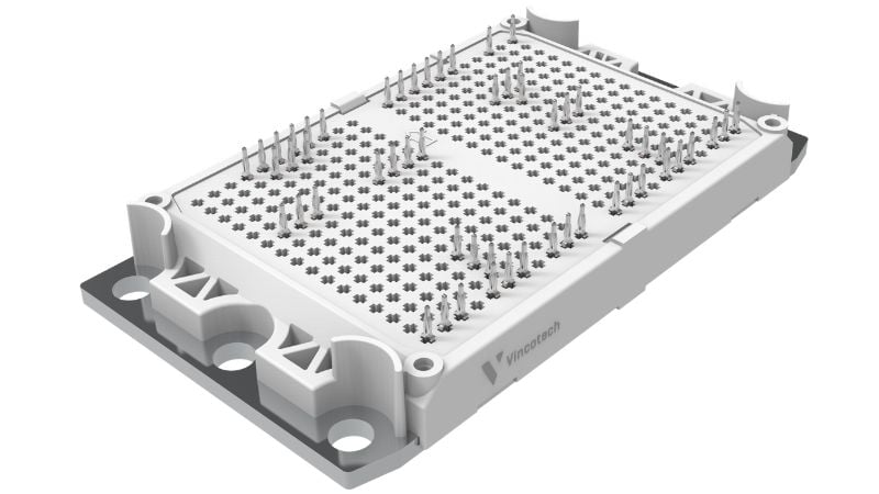
Figure 1. flow E3BP. Image used courtesy of Bodo’s Power Systems [PDF]
This module comes in a CTI600 plastic housing with isolation flaps around the heatsink mounting screws to meet insulation requirements for 2kV applications. It also offers an optional 15mm mounting height to ensure adequate creepage and clearance distances.
The 3mm convex copper baseplate eliminates local concavities along both the longitudinal and transverse edges to distribute pressure uniformly and maximize contact with the heatsink surface. This controlled curvature provides consistent, long-term stable thermal resistance and mitigates phase-change TIM (PC-TIM) pump-out. The recommended PC-TIM is qualified for continuous operation at temperatures up to 150°C. It is available pre-applied to the baseplate to streamline assembly.
Reliability Considerations
Table 1 summarizes the coefficient of thermal expansion (CTE) for different copper–ceramic–copper stack-ups. The overall CTE depends on the CTE of the ceramic material, the relative thicknesses of the ceramic core and the copper layers. Thinner ceramic layers and/or thicker copper foils increase the stack-up’s effective CTE.
Table 1. CTE of different substrate materials and thicknesses.
| Material | Thickness [mm] | CTE [ppm/K] |
| Al2O3 | 0.38 | 9.2 |
| 0.63 | 8.3 | |
| Si3N4 | 0.32 | 6.9 |
For a ceramic thickness of 0.32 mm, Si3N4 substrates exhibit an effective CTE that aligns closely with common semiconductor materials – specifically silicon (≈2.6 ppm/K) and silicon carbide (≈4 ppm/K). This excellent CTE match, combined with high fracture toughness, makes Si3N4-based substrates well suited for power modules that require long power-cycling lifetimes, as illustrated in Figure 2.
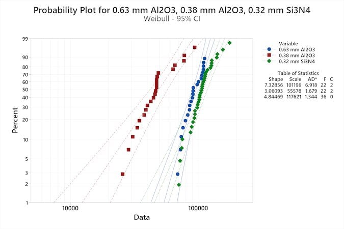
Figure 2. PCsec reliability comparison between Al2O3 (0.63 and 0.38 mm) and Si3N4 (0.32mm), Test conditions: Si IGBT, ∆T=100 K, Tj,max=150 °C, ton=0.5 s. Image used courtesy of Bodo’s Power Systems [PDF]
The green dots in Figure 2 mark failure events for the 0.32 mm Si3N4 substrate, which lasts more than twice as long as the 0.38 mm Al2O3 substrate. The 0.63 mm Al2O3 variant, represented by the blue dots, follows closely. Although this thicker ceramic performs well in terms of reliability, designers generally do not select it for baseplate-equipped modules because of its higher thermal resistance. In terms of thermal performance, the 0.38 mm Al2O3 substrate is preferred. However, it is far less reliable, as indicated by the red dots.
A PC-TIM pump-out (PCmin) reliability assessment was conducted to evaluate thermal resistance (Rth) stability under thermo-mechanical cycling. The device under test (DUT) was oriented vertically, introducing a gravitational shear component in the thermal interface material to accelerate TIM migration and represent a worst-case condition for pump-out.
The test matrix comprised flow E3BP assembled with PCTIM, flow E3BP assembled with standard thermal grease, and a competitor’s baseplate module assembled with the same grease. Table 2 indicates the defined failure thresholds and cycle counts for each configuration.
A direct comparison of the two grease-based assemblies shows that flow E3BP achieves more than twice the number of cycles. This improvement stems from the optimized baseplate geometry, which reduces mechanical movement and thereby minimizes TIM pump-out.
The durability of flow E3BP and the phase-change TIM’s high pumpout resistance improve long-term reliability. Together, they create a robust thermal interface with just 12% Rth drift after around 23,000 cycles. The test was discontinued because the chamber was scheduled for subsequent campaigns; the DUT had already exceeded the required 20,000-cycle qualification threshold, and degradation remained minimal.
Table 2. Comparison of Rth drift and cycle lifetime for different TIM types and module, Test conditions: ton=1 min, ∆T=100 K, const I, vertical orientation.
| DUT | TIM type | Rth limit | Cycles | Comment |
| flow E3BP | PC-TIM | 12% increase | 23k | Test discontinued |
| Grease | 20% increase | 14.5k | ||
| Competitor | Grease | 20% increase | 7k |
Application Example
The application example highlights the benefits of reduced thermal resistance and higher allowable operating temperatures in modern power electronics. The two graphs in Figure 3 show the transient thermal behavior of the buck IGBT in an NPC (neutral-point-clamped) topology implemented in the flow E3BP+ module under different load conditions. In the first graph, representing normal operation at 50 Hz line frequency, the junction temperature shows a periodic thermal swing, peaking at approximately 152°C. This reflects the cyclic thermal loading typical of photovoltaic inverter applications.
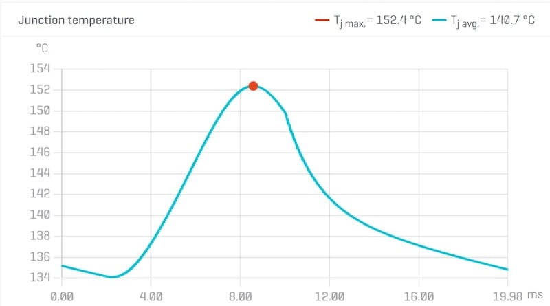
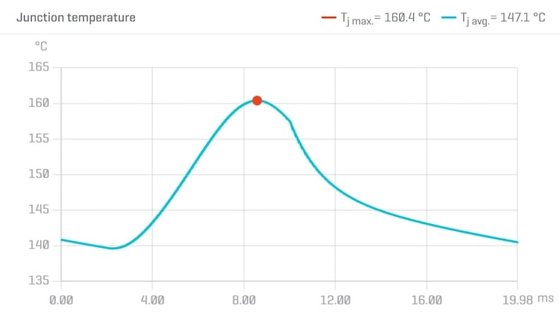
Figure 3. 465kW PV inverter buck switch temperature at normal operation (top) and overload (bottom)(Vdc=1500 V, Vac,ph=577 V, Iph=269 A, cosphi=0.8, fsw=16 kHz, Rg=4.7 Ω). Image used courtesy of Bodo’s Power Systems [PDF]
The second graph in Figure 3 shows the buck IGBT’s junction temperature under an overload condition at 1.1 × nominal output power. While the overall waveform remains similar, the higher output current increases conduction and switching losses, raising the peak junction temperature to approximately 160°C.
These results underscore the benefits of the Si3N4 substrate used in the flow E3BP+. Its Rth is around 26% lower than that of conventional substrates. This improves heat spreading and reduces junction temperature peaks under both nominal and overload conditions.
Conclusion
Si3N4 substrates and 175°C junction-temperature capability increase power density and expand operating margins in modern inverter designs. The former’s superior thermal conductivity and mechanical robustness remove major bottlenecks at the substrate level. The latter provides critical thermal headroom, giving designers greater flexibility to handle transient overloads and demanding mission profiles without compromising reliability. Together, these technologies increase power density, improve robustness, and make more efficient use of existing power-module platforms.
This article originally appeared in Bodo’s Power Systems [PDF] magazine.


