Facebook
 Google
 GitHub
 Linkedin
Maintaining Precision in Varying Temperatures
This article discusses the need for high-precision transducers and offers LEM's Ultrastab IT for industrial applications such as MRI and test equipment.
High precision transducers are becoming more in demand in high-performance industrial applications, specifically for medical equipment such as scanners and MRI machines, precision motor controllers, metering, measurement accessories and test equipment.
Most of these applications are using high precision transducers but with a limited temperature range of +10 to +50˚C, whereas many new applications require a wider temperature range while still remaining highly accurate. A good example of this would be for automotive tests benches.
However, designing and producing current and voltage transducers is LEM’s raison d’être whatever the challenges to overcome in terms of performances. The company has been the leader for years in designing and producing transducers with really high performance and competitive prices for standard markets. But it was a new challenge for LEM to build a new really high-performance family for a wider temperature range, where performances and reliability are guaranteed from -40 up to +85˚C ambient temperature at high accuracy levels. The resultant products are the Ultrastab IT 65-S, IT 205-S, IT 405-S and IT 605-S.

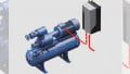
Picture 1: The Ultrastab IT xx5 high-performance current transducers series
Not only supplying high accuracy across the complete temperature range, these transducers measure all types of signals – DC, AC, pulsed and complex – and provide galvanic isolation between primary (high power) and secondary circuits (electronics). Although housed in compact cases, they match today’s power electronics requirements in terms of EMC protection with really good immunity against external electric, magnetic and electromagnetic fields.
They also meet other mandatory performances for targeted applications, such as low emissions, fast response time, large bandwidth, low phase shift and low noise. Meanwhile, high reliability and lifetime are guaranteed by the design and process quality.
This latest family is still based on fluxgate technology using a self-oscillating frequency; even if the frequency changes slightly, this technology guarantees a correct saturation of fluxgate whatever the environment in terms of temperature variation and ageing; it guarantees performances throughout the lifetime of the product and over the wider operating temperature range.
This reliability is achieved thanks to LEM’s internal design rules already used in industrial markets. These include keeping a maximum junction temperature below the worst cases of +125˚C at maximum ambient temperature, minimum burden resistance and maximum supply voltage. Additional potting material has been necessary to dissipate power losses and avoid any hot spot around electronic components. These design rules give enough margin to keep reliability levels high even in harsh conditions and wider operating temperatures.

Figure 1: Ultrastab IT xx5 series technology
The accuracy of the measurement will not only depend on the accuracy of the measuring resistor but also strongly on the sensitivity of the flux detector. However, in spite of the DC measurement function accuracy, there are some drawbacks to this DC measurement system (Figure 1). As the winding D of the flux detector is coupled with the compensation winding S, the applied square wave voltage is re-inject-ed into the compensation winding and creates a parasitic current in the measurement resistor. However, the square wave voltage induced in the S winding by this flux may be practically cancelled out when a second D’ winding (identical to D) is mounted on a second detector core inside the compensation winding S. The residual flux (the sum of the opposed fluxes in D and D’) will create very small voltage peaks that cause the remaining signal correlated with the fluxgate excitation.
The magnetic part of the transducer is represented schematically by the three cores in Figure 1. A fourth winding W is wound in between the compensation winding S on the main core to extend the frequency range of the transformer effect to lower frequencies. It is connected to an integrator that modifies the output current via the power amplifier to compensate for the too small induced voltage in a frequency range too high for the fluxgate detector.


Figures 2 and 3: Electrical offset drift and linearity error from -40 to +85˚°C – IT 605-S model – measured in ppm of IPN
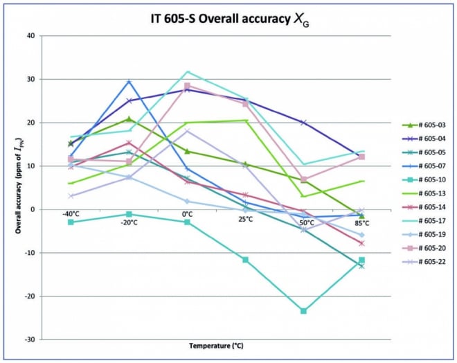
Figure 4: Overall accuracy from -40 to +85˚C – IT 605-S model – in ppm of IPN
The Ultrastab ITxx5 series has been fully characterised over its new operating temperature range of -40 to +85˚C resulting in the results shown in Figs. 2 and 3.
These show a very low drift of offset and almost no drift of linearity over the whole temperature range, resulting in a global accuracy lower than 30 ppm from -40 to +85˚C ambient temperature (Figure 4).
All these performances have been measured during type tests with high enough quantities for ±3σ value calculations to guarantee the values given in the datasheets.
Thanks to the use of an iron-nickel magnetic core and a perfect homogeneity of the winding process, accuracy in AC is very good; Fig-ure 5 gives the IT 605-S overall accuracy in AC at room temperature.

Figure 5: Overall accuracy in AC – IT 605-S model – in ppm of IPN at room temperature
This material and dedicated winding process are helpful to reach a large bandwidth and a very low phase shift, as shown in Figures. 6 and 7.

Figures 6 and 7: Amplitude and phase responses versus frequency – IT 605-S model
These frequency performances can be reached thanks to the combination of three different techniques (Figure 8):
- Fluxgate for DC up to low frequencies (few Hz);
- Pick up coil, working like a Rogowsky coil, starting at very low frequencies and compensating for the small error created by the current transformer; and
- The current transformer working up to a few hundred kHz.
Test and measurement market
Test and measurement equipment provides one of the applications requiring a wider operating temperature range. When qualifying the efficiency of power electronics-based equipment such as inverters for hybrid and electric vehicles, wind turbines or solar systems, or industrial inverters and motors, this not only provides the efficiency at ambient temperature – which can be proven by the test benches – but also the efficiency throughout the operating temperature range in real use cases.
To achieve the best efficiency, the design of the power electronics-based equipment must be such that all the components used are optimised according to their losses. Efficiency measurements for power electronics and drives components need a highly accurate power measurement system.

Figure 8: Three techniques for a large bandwidth and a low phase shift
Highly accurate LEM current transducers in the IT Ultrastab series have been used for years for the power analysis and efficiency calculations in a limited temperature range of +10 to +50˚C. The new current transducers can ensure the same functionality but over the wider operating range of -40 to +85˚C.
Active power is calculated from measured current and voltage values. The accuracy of the power value depends mainly on two parameters: measurement system.
- The accuracy of the measured current and voltage (amplitude error); and
- The phase error coming from the phase shift between the voltage and the current.
For current measurement above few amps, high accuracy current transducers are needed as interfaces connected to the power analyser. Phase error (phase shift) is a factor that cannot be ignored in this application. Indeed, the influence of a phase error increases with the decreasing of the power factor.
At power factor 1.0, there is no phase shift between current and voltage (power factor = cosine (phi) when I and U are sinusoidal functions over time); phi is the phase shift between I and U. A phase shift of only 1˚ would result in a power factor of 0.9998 at a small power error of only 0.2%. At power factor 0.1, the phase shift between voltage and current is already of 84˚. An additional phase error caused by an instrument or a transducer of 1˚ would lead to a huge power error of 17.4%.
This explains the need for high accuracy and low phase shift current measurement tools.
Meanwhile, power meters must be highly accurate to measure power at the input and output of the equipment under test as it is not possible to measure losses directly. The losses are then calculated from both values. In the worst case, the errors of both measurements are opposite. This problem increases with the efficiency of the load. Electrical drives have an efficiency of around 95%, and inverters up to 99%. Only high-precision instruments and current transducers coupled with power analysers can deliver reliable and acceptable results.
Conclusion
Optimum current transducers for measuring power over a wide operating temperature range of -40 to +85˚C, such as the new LEM Ultra-stab IT xx5 range, combine all the requirements for power measurement current transducers. Offset and linearity over the temperature range are in the 36 to 400ppm range for offset in temperature and from 8 to 12ppm for linearity in temperature; the values depend on the model used. An accuracy of 1ppm is equivalent to 0.0001%. Since the offset is so small, the transducers can be used from a few amps, and just one model can cover the entire required current measurement range; other transducers using different technologies would require the use of several transducers to cover the same range to keep this accuracy level all across the range. This brings a non-negligible cost advantage.
The phase error of all the IT xx5 transducer types is well below one minute, which is 1/60 degrees. The transducers are all galvanically isolated. DC calibrations are possible up to 16000A thanks to LEM’s ISO 17025 certified laboratory.
About the Author
Michel Ghilardi works as the R&D Programme Manager at LEM, a market leader in providing innovative and high-quality solutions for measuring electrical parameters. Its core products - current and voltage transducers - are used in a broad range of applications in drives & welding, renewable energies & power supplies, traction, high precision, conventional and green cars businesses.
Horst Bezold works as the Director at Signaltec GmbH since February 2003 where he is responsible for the power electronics analysis, efficiency analysis and wideband current and voltage transducer products of Signaltec. He has already achieved 15 publications throughout his career. He earned his Engineering Diploma in General Electrical Engineering at Technische Hochschule Nürnberg Georg Simon Ohm located in Germany.