Facebook
 Google
 GitHub
 Linkedin
Design Requirements of Transmission Line Towers
This article provides an overview of transmission line towers, covering their structural designs, functional classifications, mechanical loading considerations, and requirements for ground clearance and right-of-way.
Here, in Part 3 of our "Transmission Line Components and Design" article series, we get into details about design requirements for transmission line towers.
Transmission line towers are the primary structural elements that support overhead conductors. They must maintain a certain amount of clearance from the ground and other objects while doing so, as well as withstanding mechanical loads imposed by environmental and electrical conditions. Tower configurations vary by function, and different tower structures may be employed depending on voltage level, span requirements, terrain, and aesthetic or space constraints.
In this article, we’ll focus on the design requirements of transmission line towers. We’ll start by taking a look at the most commonly used tower structures and configurations. After that, we’ll go over important structural considerations such as conductor weight, wind pressure, and ice loading. Finally, we’ll discuss requirements for ground clearance and right-of-way.
Tower Structures
There are three common tower designs we’ll concern ourselves with:
- Lattice steel towers.
- Tubular poles.
- Monopoles.
Lattice Steel Towers
Lattice towers are the most common type used in high-voltage transmission lines (typically 220 kV and above). Built from bolted angular steel sections, they offer a high strength-to-weight ratio and excellent flexibility in design.
These towers support long spans—often over 400 meters—and can accommodate multiple circuits and bundled conductors. Their modular nature allows for easier transport and assembly, especially in remote or uneven terrain. Due to their open structure, they also perform better under high wind and ice load conditions.
Tubular Poles
Tubular poles are made from tapered, hollow steel or precast concrete sections. They’re often used in urban or suburban environments where aesthetics, space limitations, or noise considerations matter. While not suited for very long spans, they typically support spans up to 250 m and offer a smaller footprint than lattice towers. Installation is faster due to fewer components, and their closed form provides better resistance to corrosion and vandalism in some settings.
Monopoles
Monopoles consist of a single upright shaft, usually made of steel. They’re commonly used for sub-transmission or distribution lines (typically 69 kV to 138 kV). Their compact design makes them ideal for narrow rights-of-way, brownfield projects, or retrofit installations where space is restricted. While monopoles offer limited flexibility in configuration compared to lattice towers, they’re often preferred for their minimal visual impact and ease of installation in densely developed areas.
Tower Configurations
Transmission line towers are categorized based on the mechanical roles they serve within the line. Suspension towers carry conductors on straight runs, tension towers handle directional changes and mechanical stress, and transposition towers help manage line balance by rotating conductor positions. All three tower types can be seen in Figure 1.
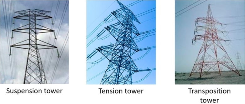
Figure 1. Types of transmission towers. Image (modified) used courtesy of MDPI
Each of these configurations is designed to address specific structural and electrical requirements that arise along the transmission path.
Suspension Towers
Suspension towers are primarily used to support conductors that run in a straight line without bearing significant longitudinal forces. They’re the most common type found along a transmission corridor. These towers rely on vertically hanging insulator strings to hold the conductors, allowing for free thermal expansion and contraction. Because they don’t resist tension along the line, they’re structurally simpler and more economical, making them suitable for long stretches between direction changes or endpoints.
Tension (Strain) Towers
Tension towers, also known as strain towers, are installed where the transmission line changes direction, terminates, or spans long distances that create high tensile forces. Unlike suspension towers, they’re built to handle substantial longitudinal mechanical loads. These towers often use horizontal, V-string, or inverted V-string insulator configurations to manage the added mechanical stress. Because they break the continuity of mechanical load paths, they also play a crucial role in isolating sections of the line for maintenance or fault protection.
Transposition Towers
Transposition towers rearrange the relative positions of conductors. This equalizes mutual inductance and capacitance between phases, minimizing line unbalance and phase coupling. It also helps reduce induced voltage in nearby communication lines and limits electromagnetic interference.
Transposition towers are strategically placed in long, three-phase transmission lines. While not required frequently, they are essential in maintaining balanced load and power quality in extended transmission networks.
Loading Considerations
The structural design of transmission towers must address various mechanical and environmental loading scenarios. These include the dead weight of conductors and insulators, vertical and horizontal loads due to wind pressure, and radial or asymmetric loads caused by ice accumulation on conductors.
Dead Weight of Conductors and Insulators
Transmission towers must be designed to safely support the static weight of all conductors, insulators, hardware, and other attachments under normal conditions. This vertical load forms the base mechanical requirement and influences the sizing of tower members, particularly cross-arms and the tower body. Consideration must be given to both continuous loads (such as the conductor self-weight) and concentrated loads (such as tension clamps and insulator strings).
Wind Loads
Horizontal wind pressure introduces significant lateral forces on the tower and suspended components. Equation 1 provides a standardized formula for this force:
$$F~=~\frac{1}{2}C_d \rho AV^2$$
Equation 1.
where:
Cd is the drag coefficient
ρ is the air density
A is the projected area (the surface area perpendicular to the wind)
V is the wind velocity.
Wind loading standards like IEC 60826 and ASCE 74 guide design based on regional wind speeds, terrain roughness, and gust effects.
As an aside, note that lattice towers typically exhibit higher aerodynamic drag compared to tubular designs due to their open-frame structure.
Ice Loads and Asymmetric Loading
In colder climates, ice accumulation on conductors and insulators significantly increases vertical loads. Ice can also form unevenly across phases, creating torsional or unbalanced lateral forces that challenge tower symmetry. These conditions must be addressed through proper cross-arm design, bracing arrangements, and phase spacing to mitigate risks of structural deformation or collapse. Ice shedding events can also trigger dynamic effects like conductor galloping or torsional oscillations.
Unbalanced and Contingency Load Scenarios
Towers must be designed to withstand unusual but realistic conditions such as conductor breakage, unbalanced ice accumulation, or extreme wind on only one or two phases. These scenarios introduce highly non-uniform loading, requiring robust tower stability under off-center forces. Structural members, foundations, and guy wires (where applicable) are analyzed under these conditions to prevent catastrophic failure.
Ground Clearance and Right-of-Way Requirements
The ground clearance and right-of-way (ROW) requirements for transmission lines address vertical and horizontal clearances, respectively. Both types of clearance are essential to ensuring safety, operational efficiency, and regulatory compliance. Proper attention to ground clearance and ROW is necessary to prevent accidents, facilitate maintenance, and otherwise reduce risks from environmental factors such as wind, ice, and vegetation growth.
Ground Clearance Requirements
Ground clearance ensures that conductors remain at a safe vertical distance above ground-level obstacles under all operating conditions, including maximum sag due to high conductor temperature and loading. Factors influencing sag include:
- Conductor type.
- Tensioning.
- Ambient temperature.
- Span length.
Figure 2 illustrates the concept of ground clearance.

Figure 2. Diagram of ground clearance for a transmission line corridor. Image used courtesy of MDPI
Minimum vertical clearances for transmission lines are typically set by national codes and vary by voltage level, terrain type, and intended land use below the line. For instance, a 230 kV transmission line typically requires a minimum ground clearance of around 7.6 m (25 ft) over highways and 5.5 m (18 ft) over open ground. These clearances also include allowances for dynamic loading, conductor swing, and potential uplift during light load or cold conditions.
ROW Requirements
As illustrated in Figure 3, ROW is the horizontal corridor allocated for the installation, operation, and maintenance of transmission lines. Its width is determined by voltage level, tower configuration, conductor blowout (lateral swing due to wind), and maintenance access requirements. For example, a double-circuit 500 kV line may require a ROW width of 60 to 80 m to maintain adequate phase-to-ground and phase-to-phase spacing during high wind or ice conditions.

Figure 3. Transmission line right-of-way (ROW). Image used courtesy of Bonneville Power Administration
ROW also ensures safety by preventing encroachment from buildings, trees, or other structures that may lead to faults or fires. Vegetation management is a critical part of ROW maintenance, particularly in wildfire-prone areas. It is often governed by utility standards or regional laws.
Regulatory and Environmental Considerations
Establishing and maintaining a transmission line ROW requires adherence to multiple regulatory frameworks, including electrical safety codes, zoning laws, and environmental protection acts. Utilities must ensure that setback distances from property lines, railways, pipelines, and water bodies meet jurisdictional requirements.
In urban or environmentally sensitive areas, ROW planning involves route optimization to minimize visual impact, land acquisition conflicts, and ecological disruption. Visual impact assessments, noise studies, and public consultations are often mandated during the planning stages to comply with state or national permitting processes.
Access and Maintenance Provisions
Beyond clearances for safety, ROW must also accommodate routine inspection, emergency response, and maintenance activities. This includes accessible pathways for service vehicles, adequate working space around towers, and stable ground conditions for the use of heavy equipment. In remote or mountainous regions, ROW design may include the construction of access roads or helicopter landing pads to ensure year-round serviceability. These logistical considerations directly affect tower spacing, line routing, and life cycle maintenance costs.
Legal and Social Aspects
Acquiring land for a transmission line right-of-way involves a complex coordination of legal, regulatory, and social considerations. Utility companies must secure easement rights—legal permissions to use a portion of private or public land for transmission infrastructure—often through negotiated compensation. These negotiations must account for land value, potential loss of use, and long-term access rights.
Resistance from landowners is not uncommon, particularly when ROW encroachment could affect property values, hinder land development potential, or alter the view. Community concerns around safety, noise, electromagnetic fields, and the disturbance of cultural or historical sites also need to be addressed. Effective ROW planning requires early coordination with local authorities, environmental bodies, and affected communities to minimize litigation risks and avoid costly project delays.
Key Takeaways
Understanding transmission tower design and its related factors is critical to building overhead lines that are mechanically stable, electrically reliable, and safe under a wide range of environmental conditions. Real-world applications require towers to withstand wind, ice, and thermal effects without structural failure or clearance violations. Selecting the appropriate tower type, optimizing conductor arrangement, and planning right-of-way access directly affect the performance and longevity of the transmission system. These decisions also influence how projects are received by communities, shaping timelines, costs, and long-term acceptance.
Countinue reading this article series wtth Part 4: "Understanding Corona Discharge in High-Voltage Transmission Lines."
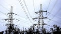
Featured image used courtesy of Adobe Stock