Facebook
 Google
 GitHub
 Linkedin
Substation Commissioning and Testing—Part 4: SCADA and Comms Systems
Learn how modern substation commissioning extends beyond plant checks to verify SCADA, comms, cybersecurity, and data integrity for safe operation and reliable event analysis.
Commissioning a modern substation is no longer limited to primary plant checks and a cursory scan of relay targets. Digital protection, automation, and enterprise integration have expanded the scope to include functional verification of SCADA and control systems, real‑time communications, cybersecurity, and data integrity through event logs and historians.
Getting this phase right is essential for safe energization, predictable operation, and clear evidence trails when analyzing events. This article organizes commissioning activities into three practical areas—SCADA and control verification, communications and integration, and energization with post‑energization checks—so that teams can progress from individual signal validation to system performance with confidence.
SCADA and Control System Testing
Substation SCADA and control testing confirms that operator actions translate into the intended field behavior, while field conditions report accurately into the control center and station HMI. A robust plan starts with I/O and data integrity, proceeds through command and interlocking tests, and finishes with time‑aware event validation that correlates protection IEDs, gateways, and historians.
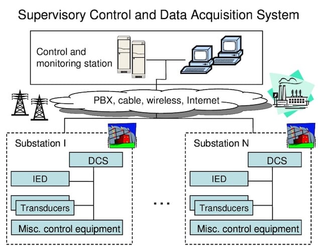
Figure 1. SCADA system for the electrical grid. Image used courtesy of ResearchGate.
I/O and Signal Verification
Status, analog, and alarm point verification: Each point defined in the database—breaker 52a/52b, isolator positions, battery chargers, transformer oil alarms, temperature sensors, feeder kW/kVAr/kV/Hz—must be proven end‑to‑end. For IEC 61850 systems, this typically includes confirming MMS reports and GOOSE inputs mapped via logical nodes such as XCBR, XSWI, MMXU, and STMP. Buffered and unbuffered report control blocks should be exercised to verify correct reporting behavior under normal and burst conditions. Reference mappings and behavior are defined in the IEC 61850 series, including Part 8‑1 for MMS and reporting.
Scaling and engineering units: Analog telemetry must be checked for correct engineering units and scale factors. For example, a CT secondary scaled at the gateway should present consistent amps and power factor across the station HMI and control center displays. For IEC 61850 MMS, confirm that data attributes and quality bits reflect valid ranges and that any gateway performing protocol translation retains units and limits consistent with the original data model. The IEC 61850 object model and service definitions give the baseline for these checks.
Alarm priority and deadband checks: Alarm philosophy should define priority, shelving, and deadbands to reduce nuisance events during switching or load swings. Applying a recognized framework like ANSI/ISA‑18.2 helps establish life‑cycle practices (rationalization, priority assignment, and consistent design). During commissioning, verify that alarm priorities align with the philosophy and that deadbands prevent chattering without masking genuine excursions.
Note: Capture screenshots or SOE exports during analog sweeps and alarm forcing tests to create a traceable record for turnover packages.
Control and Interlocking Tests
Remote open/close commands and permissives: Validate every controllable device—breakers, motor‑operated disconnects, grounding switches—by issuing commands from the station HMI and the control center, observing field indication and SOE. For 61850 stations, confirm that GOOSE‑based interlocks are active and that MMS controls honor select‑before‑operate sequences where applicable. Functional definitions and peer‑to‑peer messaging behavior are standardized in IEC 61850 (such as GOOSE for fast interlocking, MMS for controls and supervision).
Local vs. remote control authority: Authority transfer must be unambiguous. Tests should verify that local‑only control positively blocks remote commands and that status signals clearly indicate the selected source. When a device is returned to remote, verify that command execution requires proper select/execute sequences and any prerequisite permissives.
Fail‑safe behavior on communication loss: Simulate the loss of station LAN, gateway restart, or control center link. Devices must revert to defined safe states; for example, a blocked permissive should prevent a close if interlocking GOOSE messages time out. Confirm that quality flags and stale‑data indicators propagate to the HMI and SCADA, consistent with the IEC 61850 quality model and reporting behavior.
Document interlock proofs with both command logs and SOE extracts from the IEDs to ensure that logic outcomes are verifiable.
Time‑Stamped Events and SOE Validation
Accuracy of event timestamps: Sub‑millisecond to millisecond‑class accuracy is typically required to correlate fast protection actions. Precision Time Protocol (PTP, IEEE 1588) is widely used to synchronize IEDs, merging units, and gateways over Ethernet; the standard specifies methods and profiles that can achieve sub‑microsecond performance on properly engineered networks. Commissioning should verify grandmaster status, time traceability, and offset/meanPathDelay within tolerance.
Sequence‑of‑events correlation with protection IEDs: Trip, reclose, and lockout events must align across relay SOE buffers, station HMI, and the control center archive. If a GPS/PTP‑synchronized grandmaster is present, compare relay SOE timestamps to a reference and ensure consistent ordering during multi‑contingency tests.
Verification of historian data capture: Confirm that the historian captures events, analog trends, and SOE with correct timestamps and metadata. For waveform and disturbance data, test export and ingestion using the COMTRADE format, which is standardized by IEC 60255‑24 and IEEE/IEC C37.111. This ensures a common tool‑agnostic record structure for post‑event analysis.
A structured SOE validation closes the loop from IED clocks to enterprise data stores, demonstrating that incident reconstruction will be reliable.
Communication and Integration Testing
Once device‑level functions are proven, the next layer validates protocols, network resilience, and cybersecurity controls. The objective is to show that the station behaves deterministically during failures, integrates with legacy systems when needed, and restricts access according to defined roles.
IEC 61850 GOOSE and MMS verification: For peer‑to‑peer GOOSE, confirm subscription integrity, dataset content, stNum/sqNum behavior, and retransmission under simulated faults. For MMS, verify reporting (URCB/BRCB), logging, dataset updates, and control services including SBO timeouts and command termination states. The IEC 61850 series, including 8‑1 for MMS mapping and reporting, defines these behaviors; commissioning should align observed traffic with SCL‑defined datasets and control blocks.
Network redundancy and failover (PRP/HSR): Where zero‑time switchover is required, Parallel Redundancy Protocol (PRP) and High‑availability Seamless Redundancy (HSR) provide seamless recovery on link or node failure. Validate duplicate frame handling, sequence integrity, and path diversity by pulling links and power to network elements while monitoring traffic and application continuity. IEC 62439‑3 details PRP/HSR performance and topologies and is the basis for commissioning acceptance criteria.
Cybersecurity checks (authentication, role‑based access): Confirm unique accounts, credential policies, and encrypted sessions where supported. Role‑Based Access Control (RBAC) should restrict sensitive actions (such as control, configuration changes) to authorized roles across IEDs, HMIs, and gateways. IEC 62351 provides the security framework for IEC TC57 protocols; Part 8 specifies RBAC concepts for power system management and is increasingly referenced in utility policies and vendor implementations.
Verification of protocol gateways and legacy integration: Many stations bridge IEC 61850 with legacy DNP3 or IEC 60870‑5‑104 systems. Validate gateway mapping, data quality translation, and command semantics—including SBO vs. direct operate—and confirm that event, analog, and control semantics survive the protocol boundary. IEEE 1815 (DNP3) defines behavior on the legacy side, and IEEE 1815.1 provides a standardized mapping approach between DNP3 and IEC 61850, which is valuable when proving interoperability and reducing custom engineering risk.
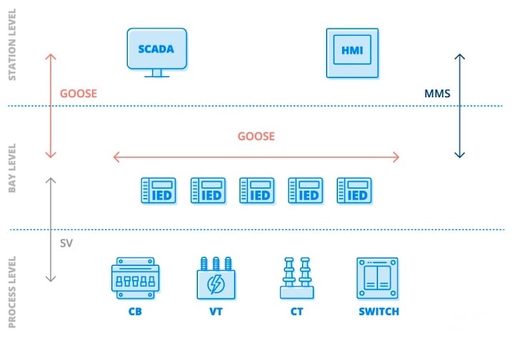
Figure 2. Functional overview of communication protocols defined in IEC 61850. Image used courtesy of SGRwin.
Energization and Post‑Energization Checks
After functional and integration testing, controlled energization proceeds with attention to transient behavior, alarms, and power system measurements. The aim is to energize safely, confirm expected power flow and phasing, and then revisit selected tests with real energy in the system.
Controlled energization sequence: Develop and rehearse a stepwise plan for bus, transformer, feeder, and capacitor/reactor energization. Include criteria for hold points and rollback. Ensure interlocks remain active during the sequence—especially for grounding switches and bypass schemes—and that permissives are not defeated by temporary overrides used during earlier testing.
Monitoring of inrush currents, voltages, and alarms: Transformer energization can produce significant inrush and harmonic content. Observe relay metering and disturbance records at first close; confirm that inrush restraint elements or harmonic blocking behave as expected and that nuisance alarms are not generated. Transformer behavior and definitions relevant to energization and harmonics are addressed in IEC 60076‑1, which can inform acceptance limits and test setup.
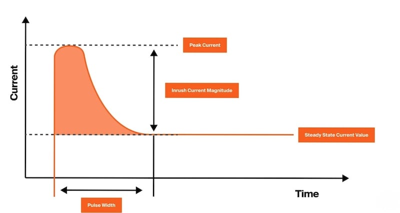
Figure 3. Transformer inrush current. Image used courtesy of Maddox Industrial Transformer.
Verification of correct power flow and phasing: Perform load checks on feeders, verify phase rotation and magnitude on metering, and compare SCADA values to field portable measurements. Mismatched PT or CT polarity and incorrect scaling must be caught here. For IEC 61850 Sampled Values or merging unit architectures, confirm dataset consistency and time alignment (relying on PTP where used) under real loading. IEEE 1588 supports the expectation for time coherence across the measurement chain.
Post‑energization inspection and retesting as required: Conduct a walkdown to check equipment status, oil or gas pressures, cooling systems, and annunciation panels. Then repeat a subset of command, SOE, and historian capture tests under live conditions—especially any tests deferred until after energization (such as capacitor bank switching alarms). Where regulatory requirements apply, align post-energization records with applicable NERC CIP documentation practices.
Note: Post‑energization records should clearly show steady‑state operation, acceptable alarm counts, and properly time‑aligned SOE and waveform captures for at least one switching event.
A Comprehensive Process
A successful substation commissioning effort validates far more than voltage on a bus. It proves that data models, controls, interlocks, time synchronization, redundancy mechanisms, and cybersecurity controls all function together as an integrated system. Starting with disciplined I/O verification and alarm design checks reduces noise in later stages.
Demonstrating deterministic behavior for GOOSE/MMS traffic and seamless redundancy builds confidence that critical automation will perform during disturbances. Verifying RBAC, authentication, and secure transport satisfies operational and compliance needs while safeguarding control paths. Finally, controlled energization—paired with targeted re‑tests under live conditions—confirms that protection and control behave as designed when it matters most. The result is a station ready for operations, backed by evidence that supports future troubleshooting and continuous improvement.