Facebook
 Google
 GitHub
 Linkedin
Time Constant in DC Circuit Inductors
This article examines time constant and energy storage in DC circuit inductors and the danger associated with charged inductors.
Inductors in DC circuits initially produce back electromotive force (EMF), limiting current flow until the losses allow it to begin. Following Ohm's Law, the inductor's current reaches its maximum level limited by circuit resistance. The time constant of inductors, influenced by inductance and resistance, dictates the speed at which the current increases and decreases during circuit switching. High inductance with lower resistance leads to longer discharge times. However, charged inductors can pose substantial dangers, generating high voltages during discharge due to the rapid change in current. Common faults in inductors involve insulation breakdown, overheating caused by incorrect voltages or mechanical defects, and broken conductors resulting from mechanical damage or connection issues.

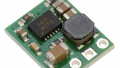
Image used courtesy of Adobe Stock
DC Circuit Inductors
In DC, the inductor produces the greatest back EMF at turn-on, which stops the current from flowing. It is the losses that allow the initial current flow. As the back EMF does not completely oppose the applied voltage, the current flow through the inductor will increase until the only limiting factor is the circuit resistance. The maximum current can be calculated by Ohm's Law, I = V/R.
The voltage drop across the inductor at this time will be zero if the inductor has zero resistance. All practical inductors will have some series resistance, so a small voltage may be measured across real inductors.
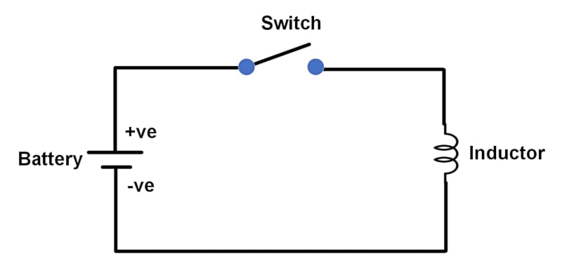
Figure 1. An inductor connected to a battery. Image used courtesy of Amna Ahmad
Time Constant
Figure 2 shows that the voltage across the inductor rises almost instantaneously to a maximum when switched on, but the current flow takes some time to reach its maximum value. The voltage across the inductor falls as the current rises until a value of approximately zero is reached.
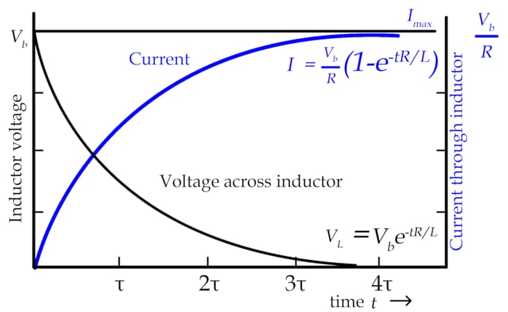
Figure 2. Current through inductor. Image used courtesy of Amna Ahmad
Similarly, the current does not immediately drop to zero when the circuit is switched off. It decreases rapidly at first and then more slowly. An inductor is, therefore, characterized by its time constant (τ = tau), which is determined using the formula:
\[\tau=\frac{L}{R}\]
where
τ = time constant in seconds
L = inductance in henrys
R = resistance in ohms
This expression shows that a greater inductance and a lower resistance will cause a longer time constant.
In one time constant, the current will increase to 63 percent of the value of the maximum current. As this increase is exponential, in theory, it will never reach its maximum value but becomes 63 percent closer with each period.
After five periods, the difference between the actual and final values will be 37 percent to the fifth power, 0.37^5, which is 0.0069 or 0.69 percent less than 100 percent, generally accepted as approximately the full value.
During discharge, when the current decreases, it decreases at the same rate as the increase. In L/R seconds, it reduces to 37 percent of the maximum value (the drop is 63 percent).
This rapid decrease in current (and flux) causes induced voltages with values many times greater than the applied voltage. The voltage is high enough to jump across the opening contacts, causing sparking that can burn the contacts. Capacitors or diodes are often used to stop or reduce these arcs.
Example 1
A 1H choke has an internal resistance of 25 Ω. Find the time constant of the choke.
\[\tau=\frac{L}{R}=\frac{1}{25}=40\,ms\]
Use the following formula to calculate the energy stored in an inductor:
\[W=\frac{1}{2}LI^{2}\]
where
W = energy in joules
L = inductance in henrys
I = current flow in amperes
This energy is stored in the electromagnetic field while the current flows but released very quickly if the circuit is turned off or power is lost. The sudden discharge can cause a very high EMF to be generated.
Example 2
A 10 H electromagnet with an internal resistance of 50 Ω has a current of 5 A. Find the energy stored in the fully charged magnetic field and the turn-off discharge time. (5 τ).
Energy stored:
\[W=\frac{1}{2}LI^{2}=\frac{1}{2}\times10\times5^{2}=125\,J\]
Discharge time:
\[\tau=\frac{L}{R}=\frac{1}{2}=40\,ms\]
\[5\tau=5\times\frac{L}{R}=5\times\frac{10}{50}=1s\]
Charged Inductor Danger
An inductor’s energy can be discharged quickly, generating a very high voltage, as E = LΔI/ΔT or the EMF generated is proportional to the change in current divided by the change in time. The voltage is high for a large inductor as the current goes from maximum to zero in a fraction of a second.
When discharged, large inductors driven by a source, such as an automotive battery, can deliver a lethal voltage across their terminals.
Three common inductor faults can cause inductors to fail.
Insulation Failure
The insulation on a conductor used in an inductor is commonly an enamel varnish, although any insulating medium might be found in various applications. If the insulation breaks down, the electricity can flow through the insulation to the ground or other coil parts.
This presents two problems: shorted turns that can cause the inductor to overheat and earth faults resulting in electric shock or RCDs tripping. Earth faults can also cause overheating if earth-fault protection is not in use and the fault current is great enough.
Overheating
A coil will overheat if the current is too great due to an incorrect voltage or the core has too little iron. If a core armature does not seat properly, the coil will overheat and often burn out. Noisy cores indicate bad mechanical seating, higher reluctance than expected, and impending failure.
Broken Conductors
An unusual but not impossible condition is a broken conductor. Conductors break when not securely fixed, often due to vibrations, or when a mechanical collision occurs with a conductor.
Conductors with soldered connections may fail if the temperature of the conductor exceeds the solder melting temperature. Improperly or loosely crimped connections may fail when the metals corrode. Many coils in electric motors are fusion-welded by melting the copper wires together. This has proven a reliable method of joining conductors in a mechanically harsh environment.
DC Circuit Inductor Takeaways
In DC circuits, inductors play a crucial role in various aspects. Understanding the time constant, determined by the inductance and resistance in the circuit, is vital for analyzing the inductor's behavior during the charging and discharging processes. This knowledge enables us to study the transient response and determine the time it takes for the inductor's current to reach its maximum or decay to zero. Inductors are also known for their ability to store electrical energy, which can be released when needed. However, it is important to be cautious of the dangers associated with charged inductors, as they retain significant electrical energy.