Facebook
 Google
 GitHub
 Linkedin
The Fundamentals of Inductors in AC Circuits
Learn about the fundamentals of inductors in AC circuits, including the concept of inductive reactance, the behavior of inductors in series and parallel configurations, and how power is influenced in inductive circuits.
In AC circuits, inductance plays a fundamental role, which is crucial to comprehending circuit analysis and design.
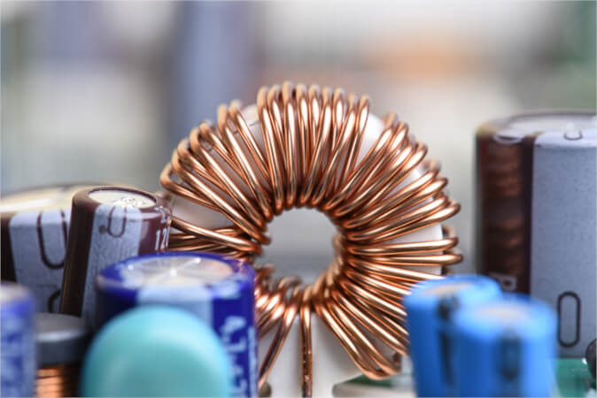
Image used courtesy of Adobe Stock
Inductance is a property of an electrical component known as an inductor, which arises when current flows through it, generating a magnetic field. This magnetic field interacts with other parts of the circuit, leading to the phenomenon of inductive reactance, a form of opposition to the change in current. Inductive reactance contributes to the overall impedance of the circuit and has significant implications for signal filtering and frequency response. Understanding inductors in series and parallel configurations is essential as it affects the total inductance and impacts the circuit's behavior. Additionally, power in inductive circuits involves a phase shift between voltage and current, resulting in complex power calculations.
In an inductive circuit, a change in current flow results in an induced EMF, which, according to Lenz's law, will oppose the change in current flow. In DC circuits, the inductive effect causes the current to rise slowly, eventually reaching approximately the maximum value of current according to the circuit resistance.
In an inductive AC circuit, the current is continually changing in value and direction, generating an induced EMF that must continually oppose the change of current flow. Figure 1 shows the relationship between a purely inductive circuit's current, induced EMF, and supply voltage.
Using the voltage phasor as the reference, the current phasor lags by 90° and is therefore drawn at right angles to the voltage reference. Remember that at maximum voltage, the current will be zero but rising, and at zero voltage, the current is at maximum.
Inductive Reactance
In AC circuits, the change in current flow generates an induced electromotive force (EMF) that opposes the current flow. The effect of this current opposition is referred to as inductive reactance (symbol XL), which is measured in ohms.
Ohm's Law states, in effect, that the current is equal to the voltage divided by the opposition to the current flow. Inductive reactance is a type of opposition to current flow; that is, for pure inductance, I = V/XL..
Inductive reactance depends on inductance and supply frequency and can be calculated from the formula:
\[X_{L}=2\pi fL\]
Where
XL = inductive reactance (Ohms)
f = frequency in hertz (Hz)
L = inductance in henrys (H)
Example 1: What would be the inductive reactance of a coil with an inductance of 0.05 H at a frequency of
(a) 30 Hz and
(b) 60 Hz, and
\[X_{L}=2\pi fL = 2\times3.142\times30\times0.05=9.43\Omega\]
\[X_{L}=2\pi fL = 2\times3.142\times60\times0.05=18.85\Omega\]
Example 2: What is the value of current flowing through a coil with an inductance of 0.12 H when a 600 V, 60 Hz supply is applied?
\[X_{L}=2\pi fL = 2\times3.142\times30\times0.12=45.2\Omega\]
\[I=\frac{V}{X_{L}}=\frac{600}{45.2}=13.3A\]
Example 3: What is the inductance of a choke coil when a 250 V, 60 Hz supply is applied, and the current through the coil is 3 A?
\[R=\frac{V}{I}=\frac{250}{3}=83.33\Omega\]
\[L=\frac{X_{L}}{2\pi f}=\frac{83.33}{2\times3.142\times60}=203mH\]
Inductors in Series
If two inductors are placed in series, each will produce an induced EMF, and the total induced EMF will be increased. The opposition to current flow is therefore increased. By placing inductors in a series, the total inductive reactance increases in the same way that placing resistors in a series increases the total resistance:
\[X_{Ltotal}=X_{L1}+X_{L2}+X_{L3}\cdot\cdot\,\cdot+X_{Ln}\]
Example 4: When two inductors, one with an inductive reactance of 10 Ω and the other with an inductive reactance of 14 Ω, are connected in series across a 250 V, 60 Hz supply,
(a) Determine the total inductive reactance.
(b) Determine the total current.
\[X_{Ltotal}=X_{L1}+X_{L2}+10+14=24\Omega\]
\[I=\frac{V}{X_{L}}=\frac{250}{24}=10.42A\]
Because the total value of induced EMF is increased, this means that the total inductance is increased. Therefore, the total inductance is found in the same way.
\[L_{total}=L_{1}+L_{2}+L_{3}
\cdot\cdot\,\cdot+L_{n}\]
Inductors in Parallel
If two pure inductors are connected in parallel, each draws its own current from the supply, and the line current is the phasor sum of the separate currents. Each current lags the voltage by 90°; therefore, they are in phase with each other and can be added arithmetically.
The total inductive reactance is therefore reduced in proportion to the increase in current, allowing us to use the same type of formula as for parallel resistors.
\[X_{Ltotal}=\frac{1}{\frac{1}{X_{L1}}+\frac{1}{X_{L2}}+\frac{1}{X_{L3}}\cdot\cdot\cdot+\frac{1}{X_{LN}}}\]
where
XLtotal = total reactance
XL1 = reactance 1
XL2 = reactance 2
XL3 = reactance 3
XLN = more reactances
The same method is used to find the total inductance of a circuit that has inductors connected in parallel
\[L_{total}=\frac{1}{\frac{1}{L_{1}}+\frac{1}{L_{2}}+\frac{1}{L_{3}}\cdot\cdot\cdot+\frac{1}{L_{N}}}\]
Where
Ltotal = total inductance
L1 = inductance 1
L2 = inductance 2
L3 = inductance 3
LN = more inductances
Example 5: When two inductors, one with an inductive reactance of 16 Ω and the other with an inductive reactance of 14 Ω, are connected in parallel across a 250 V, 60 Hz supply,
(a) Determine the total inductive reactance.
(b) Determine the total current.
\[X_{Ltotal}=\frac{1}{\frac{1}{X_{L1}}+\frac{1}{X_{L2}}}=\frac{1}{\frac{1}{16}+\frac{1}{14}}=7.468\Omega\]
\[I=\frac{V}{X_{L}}=\frac{250}{7.468}=33.48\Omega\]
Power in an Inductive Circuit
Inductors store energy as a magnetic field, which is returned to the circuit when the field collapses. This happens every half cycle, and as there is no resistance (in theory), there are no losses, and all of the energy is returned to the circuit.
Figure 1 shows the applied voltage as the red sine wave and the back EMF as the green sine wave. When the resistance either does not exist or is negligible, the back EMF is equal to the applied voltage and of opposite polarity or, as you may notice, it is out of phase by 180º.
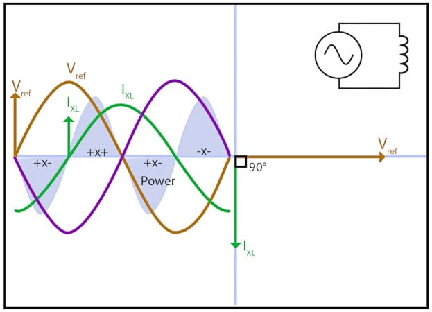
Figure 1. Power dynamics in an Inductive ac circuit. Image used courtesy of Amna Ahmad
The back EMF is proportional to the change in current flow and is therefore out of phase with the current by 90º. Similarly, the current is out of phase with the applied voltage by 90º, with maximum current flow occurring when the applied voltage changes polarity, i.e., crosses zero.
In Figure 1, the power is represented by the shaded sine wave, showing that it has twice the frequency of the voltage or current and that there are two positive pulses of power, which we generally consider energy that has been used. Now we must consider it energy that has been stored in the inductor.
The negative pulses of the power curve do not mean, however, that we have discovered negative power but that we have found energy that has been returned to the circuit.
That means the sign of the power waveform reverses every quarter of a cycle, showing that power is alternately fed into and returned from the inductor.
During the rise of the current, energy is used to create the magnetic field, while during the fall of the current, the magnetic field collapses, and the energy is restored to the supply. Over a complete cycle, the positive and negative sections of the power waveform cancel each other; therefore, the average power consumed by a pure inductor is zero.
Figure 1 also shows that the power wave is sinusoidal if the voltage and current waveforms are sinusoidal but that the frequency of the power wave is twice that of the line frequency.
Takeaways of AC Circuit Inductors
Inductors in AC circuits are key components that contribute to the behavior of electrical systems. They exhibit inductive reactance, which influences the opposition to current flow in the circuit. Understanding how inductors behave in series and parallel connections is crucial for analyzing the circuit's impedance and current characteristics. Additionally, understanding the power dynamics in inductive circuits is essential to analyze energy transfer and efficiency. By understanding these concepts, one can effectively analyze and design AC circuits involving inductors.