Facebook
 Google
 GitHub
 Linkedin
High Power Phase Controlled Thyristor (PCT) and Rectifier Diode Platform
Power efficiency is a key enabler of a greener future. This is particularly true for the industrial sector, where the demand for electrical energy is enormous, meaning improved power efficiency can make a huge positive impact on the environment.
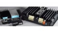
Hitachi ABB Power Grids developed a platform for Phase-Controlled Thyristors (PCT) and rectifier diodes using its latest chip manufacturing technologies that maximize performance, increase efficiency and enhance the price/performance ratio. This article provides an insight into the platform, describing the first two products – a PCT and a rectifier diode – both rated at 6500 V and supplied in the N-housing (100 mm pole piece diameter, 35 mm height).

Image used courtesy of Bodo’s Power Systems
Introduction to the Thyristor
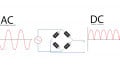
A PCT is a key component in high-power rectifiers, power supplies, motor drives, power quality systems, hydro pumping, HVDC and many more applications. It is the number one choice in applications where the highest performance, best reliability and the low conduction losses are required (see Figure 1). In some less sophisticated applications of high-power rectifiers or power supplies, the rectifier diode, providing minimal conduction losses, is also a desired solution in today’s industry.
Hitachi ABB Power Grids’ new platform for industrial thyristors and rectifier diodes boosts device performance significantly. The first products to use this new platform, a PCT and a rectifier diode, deliver a 30 percent performance increase compared to the previous generation [1] [2] [3] [4] [5]. This new platform makes use of the latest backend technologies and the leading snowflake gate design structure to create the PCT. The improved performance enables systems to become more cost efficient, a benefit that is achieved by allowing a reduction in the number of parallel connected devices in a high-power rectifier or increased output power of a static VAR compensator (SVC) or load commutated inverter (LCI).

Figure 1. Power Semiconductor devices and applications [6]. Image used courtesy of Bodo’s Power Systems
Device Design
PCT and rectifier diodes for industrial application aim for maximized junction temperature, forward and surge current ratings. Although the outline of the new products is identical to the previous generation, internally the devices are drastically different. In order to optimize ratings, three major aspects of the devices were changed:
• Wafer size
The diameter of the device was increased to the maximum with respect to the available space inside the N-housing. This resulted in a 15 percent increase in active area.
• Maximum virtual junction temperature
The maximum junction temperature was increased by 10 K. In order to withstand the increased thermal loads (e.g. higher leakage current during blocking), major changes to the silicon chip were required. Firstly, a positive-negative beveled junction termination was introduced. Additionally, the junction termination is coated with Hitachi ABB Power Grids’ latest passivation technology made of amorphous hydrogenated carbon (also known as DLC). The combination of this junction termination design with the passivation layer boosts blocking performance and provides outstanding robustness at high temperature. Consequently, the doping profile of the silicon chip could be adapted to exploit the enhanced robustness of the new junction termination, allowing on-state performance to be maximized.
• Low temperature bonding
This new platform introduces low temperature bonding of the silicon chip to the adjacent molybdenum on the anode side to thyristors and rectifier diodes. This brings multiple benefits: the silicon wafer is cooled up to the very edge, providing another mechanism to withstand increased thermal loads in addition to the adaptations and modifications of the silicon chip. Furthermore, the bonding eliminates the dry interface between molybdenum and silicon chip, leading to a lower thermal resistance between these two parts. As a result, the cooling of the silicon chip is improved, contributing to a reduction of the thermal resistance between the junction of the silicon wafer and the package’s case.
In addition to the introduction of the silicon-molybdenum bonding for PCTs and rectifier diodes, additional changes have been made to the packaging. As shown in Figure 2, the free-floating technology, used for the previous generation of PCT and rectifier diodes, is characterized by a symmetric packaging design. The dimensions of the adjacent molybdenum discs and copper pole pieces are identical for the anode and the cathode side. In contrast, the packaging of the bonded devices differs significantly. As mentioned above, the diameter of the anode pole piece has been increased to match the diameter of the chip, whereas the cathode pole piece was adapted to fit to the active area of the cathode side’s silicon chip. Due to the bonding on the anode side, the thickness of the cathode molybdenum was reduced and substituted by copper. This further improves the thermal and electrical resistances due to copper’s higher electrical and thermal conductivity. As a result of the asymmetry, however, the thermal resistances of the anode and the cathode are not equal.

Figure 2. Cross-section of the packaging for the free-floating technology (left) and bonded technology (right). Image used courtesy of Bodo’s Power Systems
The impact on the thermal resistances is summarized in Table 1. Overall the new packaging reduces the thermal resistance by 17 percent. Due to the asymmetry of the bonded devices in the new packaging, the thermal resistance on the anode side is much lower. Despite the thermal imbalance between anode and cathode, the thermal resistance of the cathode side is still reduced compared to the reference devices. Even if single-side cooling on the cathode side is used, the application will still benefit from improved thermal resistance due to the new packaging.
|
5STP 26N6500 free floating |
5STP 40N6500 bonded |
5SDD 50N5500 free floating |
5SDD 57N6500 bonded |
|
| Rth(j-c),DC,Anode | 11.4 K kW-1 | 8.5 K kW-1 - 25 % | 11.4 K kW-1 | 8.5 K kW-1 - 25 % |
| Rth(j-c),DC,Cathode | 11.4 K kW-1 | 11.0 K kW-1 - 3 % | 11.4 K kW-1 | 10.4 K kW-1 - 9 % |
| Rth(j-c),DC | 5.7 K kW-1 | 4.8 K kW-1 - 16 % | 5.7 K kW-1 | 4.7 K kW-1 - 18 % |
Table 1. Summary of thermal resistances
Device Performance
Technology Curve
The trade-off between on-state voltage drop and reverse recovery charge of the new generation compared to the previous generation and selected competitors is shown in Figure 3. The PCT decreases static losses at constant switching losses by three percent. This leads to current density increasing to 62.3 A/cm² (+11 percent), together with the reduced thermal resistance and the increased junction temperature. A similar situation exists for the diode: the static losses are reduced by three percent and the current density is increased to 79.7 A/cm² (+ eight percent). Therefore, a significant improvement in rated forward current was achieved in comparison to the previous generation.


Figure 3. Reverse recovery charge QRR vs. on-state voltage drop of the PCT and rectifier diode in comparison to the previous generation and selected competitors. QRR measured at VR = 200V for PCT and Rectifier Diode. Image used courtesy of Bodo’s Power Systems
Surge current capability
The bonding technology is one of the key factors that allow the device to withstand a higher junction temperature and avoid thermal runaway under blocking conditions. Furthermore, this technology enables significant enhanced performance at surge conditions. The surge current (PCT: I TSM, Rectifier Diode: IFSM) capability was thoroughly assessed during the product development. The main result in the case of the rectifier diode is illustrated in Figure 4, which shows the last peak value of the surge current measured during testing before the device was destroyed. The lowest last value measured during surge current testing of the new rectifier diode is approximately 145 kA in a 10 ms sinusoidal single pulse. This equals a surge current improvement compared to the previous generation of almost 60 percent. The fact that the surge current capability of the larger device from competitor A has been exceeded while being characterized by a lower on-state voltage drop, demonstrates that the enhanced surge current capability can be attributed to the silicon design and the bonding technology.
Reliability
Drastic changes were made to the chip and packaging design of this new platform for PCT and rectifier diodes. Particular attention was paid to reliability to ensure the new devices fulfil all reliability requirements according to the relevant standards. This includes high temperature reverse bias (HTRB) testing (IEC60747-6), power cycling (IEC60747-6), storage at low (-40 °C) and high (PCT: 140 °C, Rectifier Diode: 150 °C) temperature (IEC60068-2), as well as thermal cycling between those two temperatures, shock and vibration testing (IEC61373) and more. Two examples demonstrating the robustness achieved are given in Figure 5. The on-state voltage during power cycling at DT=90K and the forward leakage current during HTRB at 135 °C are given for new PCT. Both the on-state voltage and the leakage current were stable throughout testing, and no major degradation or thermal runaway was observed.
Despite the massive changes in the packaging, the latest generation of thyristors and rectifier diodes offer reliability that is fully compliant with relevant standards, meeting Hitachi ABB Power Grids’ goal to produce the highest quality products.
Ratings
The current ratings of the devices mainly depend on their forward voltage drop, thermal resistance and maximum operating temperature. As described in the previous sections, all three aspects were enhanced, leading to improved ratings. The forward current rating is increased in the range 25 percent to 35 percent and the surge current ratings by 12 percent to 15 percent, respectively. A summary of all relevant ratings of the new products in comparison to the previous generation is listed Table 2.
Summary
This article presented the specifications for the first two products based on Hitachi ABB Power Grids’ new platform for high power PCT and rectifier diodes. A performance improvement of 30 percent was achieved while maintaining the device’s footprint, allowing the new generation of devices to compete with the next larger size and elevating power efficiency to a new level. By switching to the new generation applications will benefit massively, becoming more cost efficient and delivering higher power levels.

Figure 4. Surge current testing results of the rectifier diode (5SDD 57N6500) compared to the previous generation (5SDD 50N5500) and the 5 inch competitor device. Image used courtesy of Bodo’s Power Systems


Figure 5. On-state voltage during power cycling (left) and forward leakage current in HTRB at 135 °C of 5STP 40N6500 – note that the differences in on-state during power cycling originate from the different designs under test. Image used courtesy of Bodo’s Power Systems
| Device | VDSM/RSM VDRM/ RRM | ITAVM @ Tcase = 70°C | Tvj,max | Rth(j-c), DC | ITSM / IFSM | |
| PCT | New: 5STP 40N6500* | 6500 V | 3780 A +31 % | 135 °C +10 K | 4.8 K kW-1 -16 % | 75 kA +15 % |
| Ref.: 5STP 26N6500 | 6500 V | 2810 A | 125 °C | 5.7 K kW-1 | 65 kA | |
| Rectifier Diode | New: 5SDD 57N6500* | 6500 V +500 V … 1500 V | 5700 A +25 % / +35 % | 160 °C +10 K | 4.7 K kW-1 -18 % | 82 kA +12 % / +15 % |
| Ref. 1: 5SDD 50N5500 | 5500 V 5000 V | 4570 A | 150 °C | 5.7 K kW-1 | 73 kA | |
| Ref. 2: 5SDD 50N6000 | 6000 V | 4210 A | 150 °C | 5.7 K kW-1 | 71.2 kA | |
Table 2. Key device ratings compared to the previous generation (* = Preliminary data sheet values).
References
[1] Hitachi ABB Power Grids, Semiconductors, "5STP 26N6500," 20 March 2020. [Online]. Available: https://search.abb.com/library/Download.aspx?DocumentID=5SYA1001&LanguageCode =en&DocumentPartId=&Action=Launch.
[2] Hitachi ABB Power Grids, Semiconductors, "5STP 40N6500," 01 February 2021. [Online]. Available: https://search.abb.com/library/Download.aspx?DocumentID=5SYA1086&LanguageCode =en&DocumentPartId=&Action=Launch.
[3] Hitachi ABB Power Grids, Semiconductors, "5SDD 50N5500," 02 January 2017. [Online]. Available: https://search.abb.com/ library/Download.aspx?DocumentID=5SYA1169-00&Language Code=en&DocumentPartId=&Action=Launch.
[4] Hitachi ABB Power Grids, Semiconductors, "5SDD 50N6000," 01 June 2017. [Online]. Available: https://search.abb.com/library/Download.aspx?DocumentID=5SYA%201188&Language Code=en&DocumentPartId=&Action=Launch.
[5] Hitachi ABB Power Grids, Semiconductors, "5SDD 57N6500," 21 January 2021. [Online]. Available: https://search.abb.com/ library/Download.aspx?DocumentID=5SYA1190&LanguageCode =en&DocumentPartId=&Action=Launch.
[6] M. T. Rahimo, “Ultra high voltage semiconductor power devices for grid application,” in 2010 International Electron Devices Meeting, pp. 13.4.1-13.4.4, 2010.
This article originally appeared in Bodo’s Power Systems magazine.