Facebook
 Google
 GitHub
 Linkedin
High Power Density High Performance X-Series 4500V IGBT Power Modules
This article discusses the improvements, important parameters and application of the high-performance X-Series 4500V IGBT Power Modules.
Mitsubishi Electric has developed high performance 4500V IGBT power modules providing reliable solutions for medium voltage drive, railway and power transmission applications.
Originally, Mitsubishi Electric started the development of the 4500V IGBTs in the middle of 90s. The first commercialization of standard IGBT modules in this voltage class was started at the beginning of the 2000s. It was a more efficient and compact solution compared to existing 4500V GTO press pack devices. Mainly this development was driven by railway and medium-voltage (MV) drive applications. Meanwhile, a wide variation of the 4500V IGBT modules is available, such as dual diode modules, modules with copper and AlSiC base plate, modules with standard (VISO=6 kV) and high isolation packages (VISO=10.2 kV).
Targets of 4500V X-Series IGBT Modules
The newly developed 4500V X-Series is already the third series after H-Series and R-Series of MITSUBISHI ELECTRIC IGBT power modules. The line-up of the new X-Series is expanding the existing line-up towards higher power densities (refer Figure 1). The current rating of the large package (footprint: 190mm x 140mm) increases from 900A to 1350A. On the other hand, the 900A rated current also will be made available in smaller package size of 140mm x 130mm.
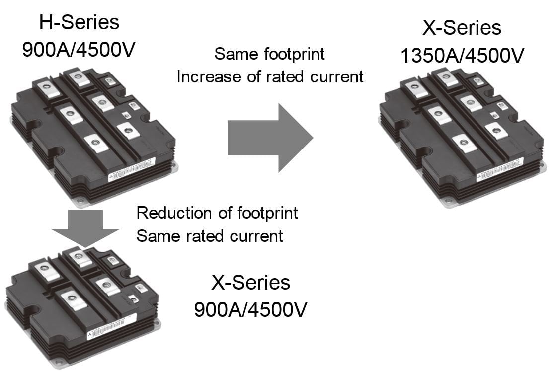
Figure 1. 4500V X-Series line-up expansion
The standard package type is still very important for different applications due to the availability of the second source from many IGBT device manufacturers and its proven reliability record in the field for many years. Furthermore, the upgrade or increase of the inverter output power is easily achieved using the widely commercially available components in the market like heatsinks, gate drivers and bus bars.
The targets for 4500V X-Series device development have been defined based on feedback from customers. These were the following:
- Increasing current rating and module power density.
- Reduction of module power losses.
- Suitable for various applications having different switching frequency ranges.
Six modules have been developed [1] to fulfill the above-mentioned market requirements. The overview of the developed 4500V X-Series modules is shown in Table 1.
Isolation voltage |
Foot print |
Type name |
VISO 10.2 kV |
190mm x 140mm |
CM1350HG-90X (VCCmax=3400V)CM1500HG-90X (VCCmax=3200V) |
130mm x 140mm |
CM900HG-90X (VCCmax=3400V)CM1000HG-90X (VCCmax=3200V) |
|
VISO 6 kV |
190mm x 140mm |
CM1350HC-90X (VCCmax=3400V)CM1500HC-90XA (VCCmax=3000V) |
Table 1: 4500V X-Series Line-up
Improving the Module Power Density
The most challenging requirement was increasing the module power density. The development target was achieved mainly by using the new 7th Gen. Chipset. The 7th Gen. IGBT chip, shown in Figure 2, contributes several significant cutting-edge features. The Carrier Stored Trench-gate Bipolar Transistor structure (CSTBT) allows reduction of the IGBT forward voltage. The new LNFLR (Linearly-Narrowed Field Limiting Ring) chip termination structure allows for an increase in the active chip area and thereby a reduction of the thermal resistance. Finally, the partial P-Collector technology allows a special capability to manage a wide RBSOA.
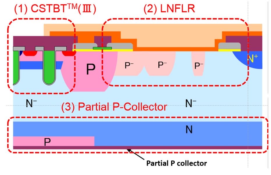
Figure 2. 4500V 7th generation chip structure
Furthermore, the overall packaging technology of 4500V X-Series is improved for managing the increased power density. The optimized internal chip layout reduces the module thermal resistance and increases the power cycling capability. As a result, the junction-to-case thermal resistance was reduced by more than 20% compared to previous R-Series (CM1350HG-90X and CM1200HG-90R). The module performance has been proven and specified for a wide operation temperature range from -50°C to 150°C. The previous 4500V module generations were specified up to 125°C.
Two different 7th chipsets are available, optimized for high and low switching frequency applications respectively. The X-Type chipset is designed for high switching frequency application (> 350Hz). The XA-type chipset achieves the lowest possible forward voltage for the IGBT and the diode. The intended switching frequency ranges from 100Hz to 350Hz. The trade-off between the forward voltage and reverse recovery switching energy for X- and XA- diode is shown in Figure 3.
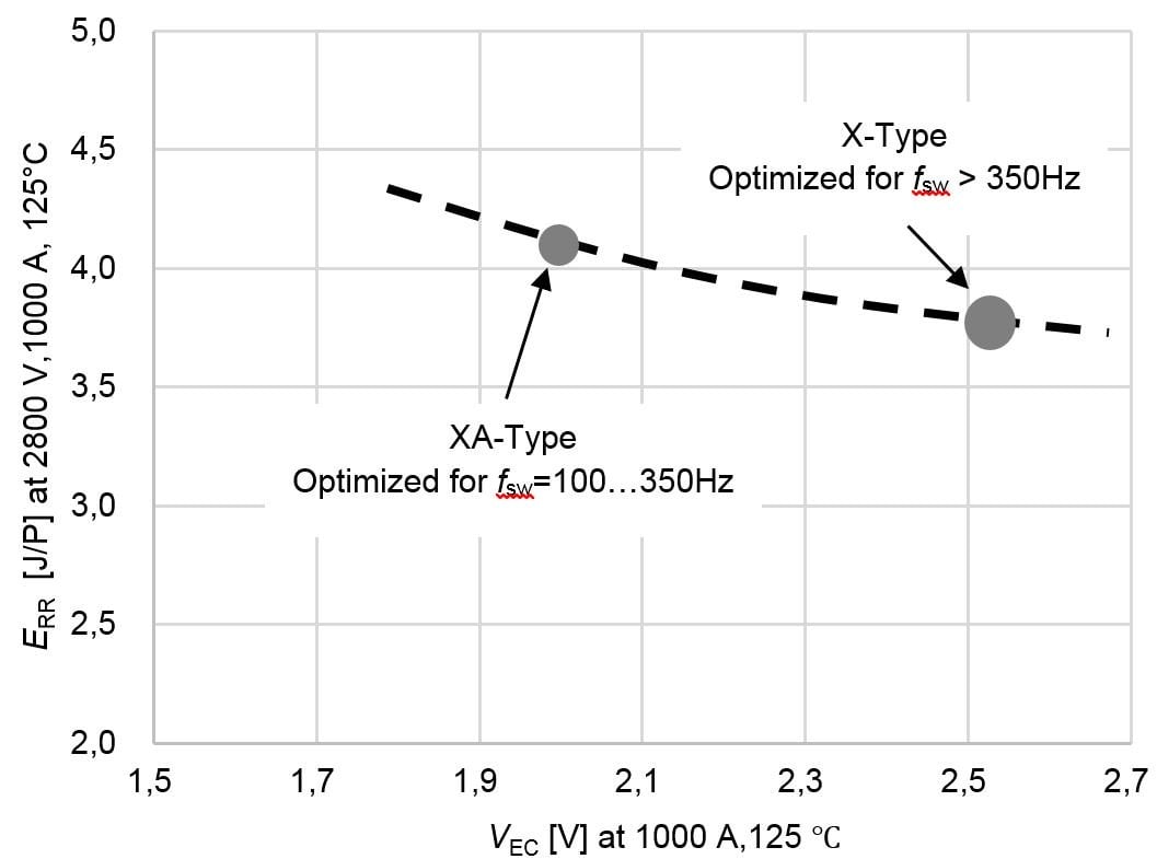
Figure 3. Diode trade-off between X- and XA device type
Safe Operating Area (SOA) for Each Application
The DC-link voltage is one of the most important stress factors influencing the SOA of IGBT module. Some applications do not require high DC-link voltage. For such cases, the SOA and with it the permitted maximum current rating increase.
The 4500V X-Series device is designed to operate at a maximum DC-link voltage of 3400V. In this case, the module’s rated current is 1350A (CM1350HG-90X). If the required maximum DC-link voltage is reduced to 3200V, the rated current increase up to 1500A (CM1500HG-90X). Both modules have the same electrical characteristics but have different SOA specifications. Each device undergoes shipping tests according to the defined maximum DC-link voltage respectively.
Example of a 3-level NPC Inverter Application
One of the targeted applications for the 4500V modules is the medium voltage (MV) drive application. For these drives, the output voltage range is between 2.3kV and 13.2kV [2]. The most common voltage levels are 3.3 kV, 4.16kV, 6kV and 6.6kV. For these output voltages, 3-level topology is widely used. For example, these voltages can be covered by devices such as the CM1500(1350)HG-90X (as shown in Table 2). For output voltage levels higher or equal than 4160V - series connection of 4500V modules becomes necessary.
Inverter output voltageVOUT[Vrms] |
Total required inverter DC-Link voltageVDC_link[V] |
IGBT blocking voltageVCES IGBT[V] |
IGBT Seriesconnection |
IGBT DC-Link voltageVCC_IGBT[V] |
3300 |
4800 |
4500
|
No |
2400 |
4160 |
6200 |
4500
|
Yes |
1600 |
6000 |
8800 |
4500
|
Yes |
2200 |
6600 |
9600 |
4500
|
Yes |
2400 |
Table 2. Example for 4500V IGBT module based 3-level NPC configurations
Scalability towards lower power ranges can be realized with the CM900HG-90X device or the H- and R-Series modules. The following example shows the potential of the new X-Series compared to the first H-Series in terms of power loss reduction.
For the VOUT=3300V output voltage, the necessary DC-Link voltage is about 4800V. In 3-level NPC-configurations, the IGBT module would experience half the total DC-Link (2400V). In case the heatsink potential would be connected to the middle of the DC-Link the IGBT Module isolation voltage of 10.2 kV(rms) would be sufficient to cover in Table 2 mentioned inverter output voltages.
Figure 4 shows the power loss simulation versus output current for CM900HG-90H H-Series device and CM1350HG-90X X-Series device. The simulation conditions are:
- Switching frequency fsw=0.5kHz,
- Power factor p.f.=0.85,
- Modulation index m=1,
- Junction temperature TJ=125°C.
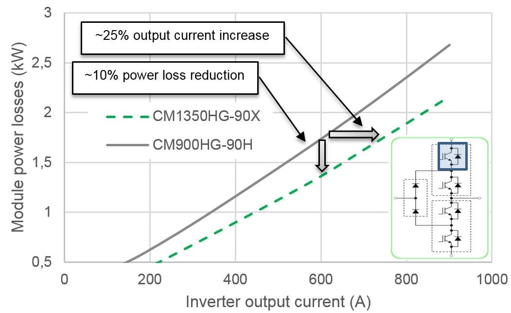
Figure 4. Comparison of the power loss simulation result using the H- and X-Series 190mm x 140mm modules.
There are two possibilities for utilizing the performance of new X-Series power modules. One possibility is a reduction of the IGBT module power losses. The power losses decrease by about 10% compared to the H-Series. The other possibility is increasing the inverter output current. The output current can be increased by about 25% compared to the H-Series. In addition, 150°C operation of X-series enables to increase even more output current than 125°C operation.
The Key Benefits of the 4500V X-Series
The newly developed 4500V X-Series enables a significant increase in the inverter output power. Key enabling factors are an increased maximum junction temperature of 150°C, an improved thermal management and reduced power losses in the module. A large line-up and backward compatibility to H-Series and R-Series ensures a flexible converter design and an easy design-in. Furthermore, two different chip sets (X-type and XA-type) facilitates the optimal operation at required switching frequencies.
About the Authors
Eugen Wiesner is an Application Engineer at Mitsubishi Electric Europe B.V., Ratingen Germany, one of the branches of the Japanese multinational electronics and electrical equipment company, Mitsubishi Electric Corporation. the company manufactures electrical and architectural equipment and is one of the major producers of photovoltaic panels.
Nils Soltau is an Application Engineer at Mitsubishi Electric Europe B.V. He received his Diploma degree in electrical engineering and information technology from RWTH Aachen University, Aachen, Germany, in 2010. Since March 2010, he has been with the Institute for Power Generation and Storage Systems (PGS), E.ON Energy Research Center, RWTH Aachen University, where he builds up a 5 MW DC-DC converter. His research interests include high-power DC-DC converters, medium-voltage power semiconductors, and magnetic components.
Eugen Stumpf is the Application Engineering Manager at Mitsubishi Electric Europe B.V., one of the branches of the Japanese multinational electronics and electrical equipment company, Mitsubishi Electric Corporation. the company manufactures electrical and architectural equipment and is one of the major producers of photovoltaic panels.
Kenji Hatori works as an Assistant Manager on Project Management at the Mitsubishi Electric Corporation, Fukuoka Japan, a branch of the Japanese multinational electronics and electrical equipment company, Mitsubishi Electric Corporation, that specializes in power device works.
Hitoshi Uemura works at the Mitsubishi Electric Corporation, Fukuoka Japan, a branch of Mitsubishi Electric Corporation which is one of the world's leading names in the manufacture and sales of electrical and electronic products and systems used in a broad range of fields and applications.
References
- Mitsubishi Electric Corporation, “Mitsubishi Electric to Expand Lineup of X-Series HVIGBT Modules,” Press Release No. 3094, May 2017
- Prof. Dr. M. Hiller, “Leistungselektronik mit Si-Bauelementen für die Mittelspannung”, Tagungsband des 1. Industriearbeitskreis Mittelspannungs-Leistungelektronik [Proceedings of the 1. Industry Working Group Medium-Voltage Power Electronics], Fraunhofer ISE, Berlin, Germany, 2016.