Facebook
 Google
 GitHub
 Linkedin
Pushing Module Power Density to the Limit
Full SiC MOSFET modules have clear performance benefits, especially where high power density is required, but how can the highest possible power density be achieved?
This article is published by EE Power as part of an exclusive digital content partnership with Bodo’s Power Systems.
Mega trends like climate change, demographic shifts, and urbanization are changing the world. These drive industry trends with energy efficiency, green energy, and electrification—key topics that raise new requirements and challenges. Engineers are aiming to realize these new requirements in the next generation of inverter designs, and the challenges of high efficiency, high power density, and high reliability of power electronics modules need to be supported by continuous module improvements. Full SiC MOSFET modules with blocking voltages of 1700V and 3300V have been successfully developed from the research stage to mass production and meet the highest traction quality, reliability, and performance standards.
Package and Chip Shift
Over recent years, the next High Power Density Dual (nHPD2) power module has been widely adopted as the new de-facto standard power module outline for new converter designs [1]. The new module platform delivers many performance improvements over older IHM packages, including the very low module stray inductance and other optimizations that make this module suitable for the adoption of SiC MOSFETs while also offering performance benefits with silicon IGBTs. Some of the key benefits of the new dual module are:
- Equipped with both silicon IGBT and SiC MOSFET, providing the right technology for all converter requirements
- Very high-power density enabling compact cost-effective converter designs
- Optimized low inductive package for clean low loss switching
- Dual package connection, standard and easy to use
- Parallel connection capability, minimized footprint, and easy power increase
- Enables modular inverter platforms for different power levels and voltage classes
- Interchangeable modules with different current ratings
The nHPD2 is a key component enabling the next generation of converter system designs with a focus on efficient, power-dense, and cost-effective design.
After many years of research and development, high-power, high-voltage SiC MOSFET modules are now part of mainstream converter designs and ready to support the requirements of state-of-the-art converters with low loss, high power density, and high reliability and robustness meeting market standards, including in the railway world. SiC MOSFET modules are already enabling significant system-level optimization where low switching losses can be utilized to increase switching frequency and optimize magnetic component size, cost, and losses, increase current density, reduce cooling power, and improve efficiency. Overall, the system optimization scope has been increased, providing engineers with more options to optimize their system to their particular challenges and requirements [2].
Figure 1 shows the chip and packaging technology roadmap from Hitachi. This timeline presents the vast development of Hitachi´s power device product line-up and gives an outlook on future developments. The trend is continuous development to improve the performance of both chip and package technologies to meet the requirements of diverse high-power systems.
Hitachi’s new high-speed planar SiC MOS provides very low switching losses and is combined with copper-sintered chip bonds in the latest SiC MOSFET modules to enable junction temperatures up to 175°C while providing the highest levels of power cycle durability.

Figure 1. Timeline showing power density increase driven by technology over time. Image used courtesy of Bodo’s Power Systems [PDF]
Copper Sintering
Using copper sintering for the die attachment dramatically increases the power cycle durability of the module while also lowering the thermal impedance and increasing the allowable junction temperature [3]. This combination enables significant improvements in output current, especially in applications with high power cycle requirements. Figure 2 shows the cross-section of a power module with the copper sintered layer highlighted. A microscope image of the real structure is shown enlarged in the lower half of the image.

Figure 2. Cross section of a power module showing the main layers (top). A microscope zoom shows the sintered Cu layer (bottom) which achieves improved thermal conductivity and increased power cycling durability. Image used courtesy of Bodo’s Power Systems [PDF]
Optimizations at the Baseplate
Widening the power density envelope further, the interface between the module baseplate and the heatsink shows further improvement potential. Pin-fin baseplates for direct water cooling provide lower thermal impedance between the module and coolant [4]. The concept of direct water cooling is widely adopted in the automotive industry and extensive PinFin module design experience can be transferred to high power modules.
Hitachi is running concept studies where the benefits and commercialization are being evaluated. Moving from a closed (flat baseplate modules) to an open (for pin-fin baseplate modules) water cooling system raises new considerations for the system designer including implications for maintenance but the potential increase in power density of the converter is clear and significant.
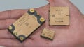
Modules with pre-applied thermal interface material (TIM) are another optimization in the near term. The main advantage is to replace the application of thermal grease during converter assembly and enable improved converter manufacturing efficiency. Figure 3 shows the pin-fin baseplate and two different printed TIM images.

Figure 3. nHPD2 product baseplate options. PinFin (left) and pre-applied TIM with two different printed images to achieve optimized thermal conductivity (right). Image used courtesy of Bodo’s Power Systems [PDF]
High-Voltage Full SiC nHPD² Package
The next nHPD² is Hitachi´s optimized package to achieve future requirements with the application of the technologies discussed so far developed and manufactured with a deep vertical integration of all processes. The chain of research, development, and production allows continuous improvements of chip and package technologies with a focus on delivering the best-performance products.
Figure 4 shows the SiC module line-up. From this line-up, the MSM800GS33ALT and MSM900GS17CLT [5] have been tested and simulated in the European Power Lab located in the UK. The test and simulation results are presented in the test and simulation section of this article.

Figure 4. Hitachi´s Full SiC MOSFET module line-up with 1700V and 3300V blocking voltage. CLT indicates the high-speed chip. Test and simulation results of both MSM800GS33ALT and MSM900GS17CLT are presented in this article. Image used courtesy of Bodo’s Power Systems [PDF]
Lab Test and Simulation Results
Methodology
A combination of testing and simulation is used to investigate the maximum available output power that can be delivered from each module type. Two module types have been investigated: 1.7 kV 900 A and 3.3 kV 800 A. The impact of the technologies discussed above is investigated, and the maximum output current is determined for each technology applied in turn. Output current is used in the results as it is the directly measured value from the tests, but of course, it is directly proportional to output power.
Double pulse testing was undertaken in the European Power Lab to measure the switching losses across a wide range of operating conditions, including voltage, current, temperature, and gate resistance. The results were used to create multi-dimensional device models for use in Plecs simulations.
Using a two-level, three-phase converter model, the losses and junction temperatures of the modules were simulated at steady state conditions with typical converter conditions across a range of operating points with varying current (in 50 Arms intervals) and switching frequency (1 kHz to 10 kHz). For each version of the module and each switching frequency, the highest current is identified where the maximum junction temperature of the module is less than 160°C. This includes the temperature ripple in the module and provides a suitable design margin from the maximum allowable junction temperature of 175°C. As the simulations are conducted in 50 A intervals the results presented show the minimum bound for maximum output current, i.e. the actual maximum output current will be higher than the results presented. 3300 V high-speed MOSFETs (CLT type) results are based on preliminary test data and performance curves.
As 1700 V high-speed SiC MOSFETs are already available from production, the standard (ALT type) 1700 V has been omitted from this study.
The performance steps investigated are:
1. Baseline: Standard 3300 V SiC MOSFET (ALT type) with datasheet test conditions
2. Optimised Drive: Standard 3300 V SiC MOSFET (ALT type) with optimized Rg and Vge values
3. High Speed: High-speed 3300 V and 1700 V SiC MOSFET (CLT type) with optimized Rg and Vge values
4. PinFin: High-speed 3300 V and 1700 V SiC MOSFET (CLT type) with optimized Rg and Vge values and PinFin baseplate
Results
Baseline to Optimized Drive
An important first step is optimizing the driving conditions for the MOSFET in the application conditions. This is particularly important for Hitachi modules where the performance presented in the datasheets is notoriously conservative. Reducing gate resistance (Rg) and increasing gate-emitter voltage (Vge) enables an increase in available output power of more than 25% across most switching frequencies, rising to a 50% increase at 10 kHz for standard 3300 V SiC and a 10% to 25% increase across most switching frequencies for high-speed 1700 V SiC as shown in Figure 5.

Image used courtesy of Bodo’s Power Systems [PDF]

Figure 5. Maximum output Current for 3300V modules (top) and 1700V modules (bottom) when Gate Drive optimization is applied. Image used courtesy of Bodo’s Power Systems [PDF]
High-Speed SiC
Hitachi’s high-speed SiC, shown as CLT in the module type name, delivers a significant reduction in switching losses. This enables an increase of 15% to 30% increase in output power, with the effects greatest at higher switching frequencies, as shown in Figure 6.

Figure 6. Maximum output Current for 3300 V modules high-speed MOSFETs are applied. Image used courtesy of Bodo’s Power Systems [PDF]
PinFin Baseplate
Changing the flat baseplate of the module to a PinFin baseplate for direct water cooling delivers a large decrease in thermal resistance, therefore allowing more heat to be removed from the chips and a higher output current. This enables a 15%-20% increase in output power from the module, as shown in Figure 7.

Image used courtesy of Bodo’s Power Systems [PDF]

Figure 7. Maximum output current for 3300 V modules (top) and 1700 V modules (bottom) when PinFin baseplates are applied. Image used courtesy of Bodo’s Power Systems [PDF]
Combined Effect
The combined effect of these technology deployments and optimizations enables the output power to be increased by 30%, with 65% possible at higher switching frequencies. When compared to the standard SiC (ALT type) evaluated from the datasheet values, the output power more than doubles, as shown in Figure 8.

Image used courtesy of Bodo’s Power Systems [PDF]

Figure 8. Maximum output current for 3300 V modules (top) and 1700 V modules (bottom) when gate drive optimization, high-speed MOSFETs, and PinFin baseplates are applied. Image used courtesy of Bodo’s Power Systems [PDF]
Simulation Parameters
Addressing the key challenges of cost, size, and efficiency in electrifying and decarbonizing the world power SiC MOSFET modules have a key role to play. Hitachi’s full SiC MOSFET nHPD2 modules are equipped with the latest high-speed MOSFETs for low loss and state-of-the-art packaging technology to deliver their full performance reliably and dependably over a very long time.
Table 1. Simulation Parameters
| 1700 V modules | 3300 V modules | |
| Switching Frequency (Fsw) | 1 kHz to 10 kHz in 1 kHz steps | |
| Output Current (Iout) | 50 Arms to twice rated | |
| DC Link Voltage (Vdc) | 900 V | 1800 V |
| Output Frequency (Fout) | 50 Hz | |
| Modulation depth (m) | 0.9 | |
| Power Factor | 0.9 | |
| Deadtime | 0.1 us | |
| Modulation Scheme | Sine PWM | |
| Leading/Lagging | Lagging (Inductive) | |
| Ambient Temperature (Tamb) | 40 DegC | |
| Heatsink Thermal Resistance (Rth) | 0.015 k/kW per module = 0.03 k/kW per switch position | |
| Contact Thermal Resistance (Rth ch) | 0.02 k/kW | |
References
[1] D. Kawase, K. Nagashima, T. Hirayama, K. Azuma, et al: nHPD2 (next High-Power Density Dual) with next generation chip suitable for low internal inductance package, Proc, PCIM Europe 2016
[2] P. Bhatnagar, C. White: Benefits of Using the New 1700V and 3300V High Power Modules for Traction Applications, Bodo’s Power Systems; February 2022
[3] T. Arai et al: 3.3 kV 800 A Next High Power Density Dual Si IGBT Module with High Power Cycle Durability, Proc, PCIM Europe 2022
[4] H. Nishimori et al: Direct-Liquid-Cooled Next High Power Density Dual (nHPD2) using Copper Base Plate, Proc, PCIM Europe 2022
[5] https://www.hitachi-power-semiconductor-device.co.jp/en/products/igbt/ index.html
This article originally appeared in Bodo’s Power Systems [PDF] magazine.