Facebook
 Google
 GitHub
 Linkedin
Finding Irregular Effects in Control Loop Designs
An oscilloscope with digital trigger technology helps identify irregular events in the control loop of power converters.
This article is published by EEPower as part of an exclusive digital content partnership with Bodo’s Power Systems.
Stable operation is essential for power converters under all circumstances. Most converter types have different working conditions, such as load steps, startup/shutdown sequences, and input voltage variation. In addition to the standard feedback control loop, integrated pulse width modulation (PWM) controllers provide extended functions, such as line feed-forward loop control and soft-start control.
These extended control functions improve regulation for specific conditions. Such complex regulation systems require smart methods to ensure proper converter operation in all modes. Extensive expertise and the right measurement tools are essential for identifying and locating unexpected events in the system.
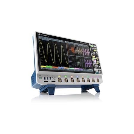
Oscilloscopes with a sensible digital trigger and large memory, such as the R&S MXO 5 from Rohde & Schwarz, can analyze the behavior of power converters. Image used courtesy of Bodo’s Power Systems [PDF]
A power converter’s design and stability must be validated in all operational modes. Generally, pulse width modulation controllers provide multiple functions, which may increase complexity and require a smart validation approach. Examples include line feed-forward loop control and soft-start control. Soft-start control is a specific mode: when the converter starts, the positive duty cycle is gradually increased to ramp up the output voltage smoothly to limit inrush current and overall electrical stress.
During this timeframe, the duty cycle varies from low numbers to a higher value until the output voltage has reached a steady state condition. Once the sequence is complete, the standard control feedback loop regulates the output voltage to the target value. In addition, a line feed-forward loop might be active to optimize the output voltage regulation while the input voltage changes rapidly. Both control mechanisms coexist, making detecting and locating unexpected or unstable operations difficult. Noise naturally exists in switching converter designs and may lead to improper loop regulation. This instability in control loops can be detected by triggering voltage variation or, better still, by monitoring the width of the positive duty cycle since the duty cycle is used to regulate the power plant to keep the output voltage constant. A complex triggering capability is mandatory to detect any irregular event in such a complex control system.
Oscilloscopes With Complex Triggering Capability
Test engineers need an oscilloscope based on digital trigger technology for this challenging task. Rohde & Schwarz has equipped its MXO 4 and the MXO 5 oscilloscope series with a sensitive digital trigger of 0.0001/div. They offer a resolution of up to 18-bit in high-definition mode. Since two trigger conditions are essential to finding variations of the positive duty cycle after the soft-start period has elapsed, the oscilloscope also allows the definition of complex trigger conditions. Figure 1 shows the trigger conditions at converter startup.
Trigger condition A detects the end of the soft-start ramp and is configured as the window trigger. The output voltage must be within a defined range. The trigger type for condition B can be based on PWM pulse width.
The width trigger will detect any values outside a defined range of the positive duty cycle. This can easily occur due to an improper design of the line feed-forward control filter. However, if the converter is in a steady state, there will be no significant duty cycle variations. If the positive duty cycle deviates from a valid range due to an unexpected event, condition B will trigger and stop the acquisition. This helps to isolate this specific event, and the user can discover the root cause of this irregular control event.
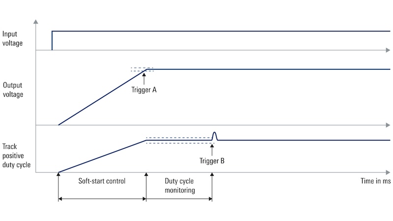
Figure 1. Complex trigger definition to detect irregular effects. Image used courtesy of Bodo’s Power Systems [PDF]
Analyzing DC/DC Switching Converter Behavior
A DC/DC switching converter in full bridge topology with synchronous rectification is used to showcase the complex triggering with an R&S MXO 5. Handling with an R&S MXO 4 oscilloscope is identical. The isolated converter operates at a switching frequency of 100 kHz and converts the input voltage of 48 V to an output voltage of 12 V. The output current is specified to be a maximum of 8 A. The digital controller used in this application enables the user to activate, deactivate, and modify the line feedforward control.

Figure 2. Trigger sequence window. Image used courtesy of Bodo’s Power Systems [PDF]
Step-by-Step Device Setup
To configure a complex trigger:
- Set up a suitable channel, including proper probe selection
- Activate a trigger sequence and define an appropriate reset timeout (Figure 2)
- Define trigger A as window type, including upper and lower level, to catch the end of the soft start during startup (Figure 3)
- Activate the positive duty cycle measurement function and define the reference levels, e.g., 20/50/80 % of the voltage
- Define trigger B as width type and set the width and delta time (Figure 4)
- Activate the duty cycle measurement function, including the track function
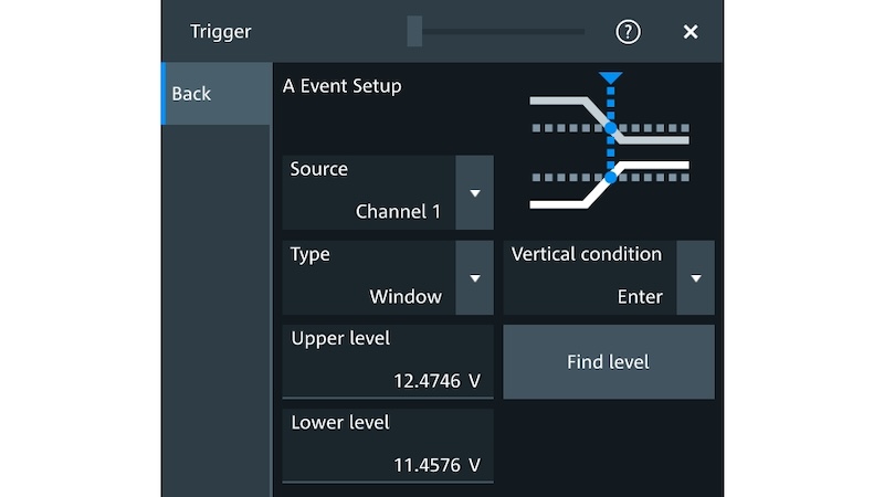
Figure 3. Trigger event A window. Image used courtesy of Bodo’s Power Systems [PDF]
Measuring the Load Transient
After being set up, the converter starts, and the soft-start procedure is executed. The instrument waits for any variation in the duty cycle measurement as soon as the trigger detects a valid trigger for condition A. Assuming a constant load after the soft start, the instrument will not trigger at condition B because the duty cycle should remain constant.

Figure 4. Trigger event B window. Image used courtesy of Bodo’s Power Systems [PDF]
To showcase this complex trigger sequence, the line feed-forward function was activated inside the controller of the converter with an improper digital filter design. As a result, the instrument was also triggered at condition B. The recorded measurement is shown in Figure 5, where the output voltage is measured on channel 1, and the input voltage is measured on channel 3. Channel 2 shows an internal signal of the controller, which reflects the input voltage to the secondary side. The M2 channel shows channel 2 filtered by a lowpass filter through the math function. Furthermore, the PWM control signal (channel 4) and the positive duty cycle track waveform are displayed in the bottom window.
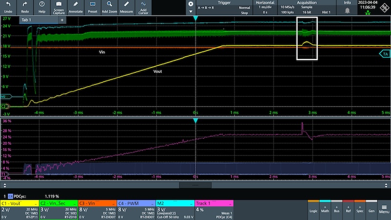
Figure 5. Startup of the converter and irregular control effects. Image used courtesy of Bodo’s Power Systems [PDF]
Three ms after the soft-start sequence has elapsed, the instrument triggers at condition B because the duty cycle shows a positive step followed by a negative drop. This duty cycle variation is only present when the line feed-forward is activated. The next step would be to optimize the acquisition length, which is now possible due to the complex trigger sequence. The result is shown in Figure 6.
In this case, more details become visible with increased accuracy, giving the user a better understanding of the system. The user may start the process and find the root cause efficiently.
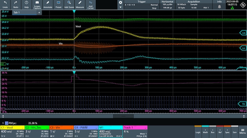
Figure 6. Irregular control effects at trigger condition B. Image used courtesy of Bodo’s Power Systems [PDF]
Identifying Irregular Events
To identify irregular events in the control loop of power converters, test engineers need an oscilloscope with digital trigger technology. These instruments enable them to efficiently define complex trigger events to isolate the root cause. In addition, they should choose an oscilloscope with a large memory that allows them to add additional functions, such as the track on duty cycle, where a high sample rate is required over a long acquisition time.
This article originally appeared in Bodo’s Power Systems [PDF] magazine.