Facebook
 Google
 GitHub
 Linkedin
Pulse Width Modulation vs. Sinusoidal Control in Stepper Motors
The article examines pulse width modulation and sinusoidal control methods in stepper motors.
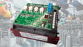
Stepper motors are an essential component in industrial systems that need precise motion control. They rely on motor drives to decode pulse input and generate output current. A good control system generates current for the motor winding using a specific algorithm to make precise increments in stepper motor rotation. The algorithm controls speed, position, step resolution, and efficiency. Control methods like pulse width modulation (PWM) and sinusoidal control generate the needed current for precise motion control.

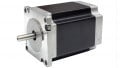
Disassembled stepper motor. Image used courtesy of Adobe Stock
How Pulse-Width Modulation Works
PWM is a control method for regulating the amount of power delivered to loads like motors. This method changes the width of the electrical pulse, which is essential for motor control.
In PWM, a microcontroller, timer, or other circuitry generates a digital signal, typically a square wave. The signal generated is amplified by a driver circuit, which sends it to the load. The amount of power delivered to the load depends on the pulse width.
The duty cycle is used to vary the pulse width of the digital signal (off). A pulse-width modulator, which controls the pulse width by comparing a reference voltage to a ramp voltage, is typically used to adjust the duty cycle.

Figure 1. The PWM signal is solid square waves of the original signal (dashed). Image used courtesy of Bob Odhiambo
Varying the PWM signal’s duty cycle allows for adjustment of power delivered for precision control, making it an ideal control method for stepper motors.
Types of PWM Signals
There are two distinct types of pulse width modulation signals.
Single-ended PWM. In single-ended pulse width modulation, a microcontroller generates square-wave signals with a varying duty cycle and a fixed frequency. This frequency determines the rate at which the pulse is sent. The width of the pulse is its duty cycle. The cycle can be varied to define the percentage of time the pulse is high compared to the total cycle time.
Differential PWM. In this type of PWM, the duty cycle is controlled by two waveforms. One is a modulated signal with varying amplitude and phase, while the other is a duty cycle control waveform. The waveform generated with the duty cycle is based on the modulating signal and is combined using an analog multiplier. This type of PWM is used in motor control applications for precision control.
Duty Cycle Calculations
The duty cycle is the pulse width ratio to the period, crucial to controlling the stepper motor signal.

Figure 2. Pulse width modulation, amplitude, pulse width, and period are essential for calculating the duty cycle of the pulse. Image used courtesy of Bob Odhiambo
To calculate the duty cycle, use the following formula:
\[Duty\,Cycle=\frac{Ton}{Ton+Toff}\times 100\%\]
Where Ton is when the device is on or active, and Toff is when it is off or inactive.
Ton and Toff can also be considered as the highs and lows of the PWM signal.
For example:
Consider a device that is on for 2 seconds and off for 8 seconds in 10 seconds. The duty cycle can be determined by
\[Duty\,Cycle=\frac{2}{(2+8)}\times100\%=20\%\]
The device's duty cycle is 20%, making it inactive 80% of the total time.
How Sinusoidal Control Works
The sinusoidal method is another way to control the voltage delivered to the stepper motor. It does it naturally, like a sinusoidal waveform in AC power. This method is smoother and more accurate than PWM.
In a sinusoidal control system, a waveform generator generates a sine wave with a fixed amplitude and frequency. For stepper motor control using this wave, a measure of the motor’s position is fed into a control circuit for comparison with the sine wave.
After acquiring and comparing the motor measurements with the sine wave reference, the power delivered to the motor is adjusted by modifying the width and timing of pulses in the PWM signal. This signal is amplified by a driver circuit and sent to the motor to drive it.
Sinusoidal control is more efficient and precise in controlling stepper motors with minimal vibrations and noise. This type of control can be employed in stepper motors, power converters, and inverters.
Comparing PWM and Sinusoidal Control
Below is a comparison of sinusoidal and PWM control.
- Efficiency: Sinusoidal control delivers power more efficiently, especially in high-speed operations, as it delivers power continuously. This type of power delivery reduces heat generation and electrical noise in the system.
- Control method: Sinusoidal control matches the shape of a sine wave in adjusting power delivery, while PWM works by rapidly switching power on and off.
- Complexity: PWM control is generally simpler to implement than sinusoidal control, which requires a complex control algorithm and additional circuitry. Sinusoidal control is difficult to implement, design, and troubleshoot.
- Accuracy: Sinusoidal control is more accurate than PWM as it provides real-time adjustment of stable and more consistent power delivery to match the sine wave reference.
- Application: PWM is used in applications such as stepper motor control, power converters, and inverters, while sinusoidal control is used in high-precision and power-efficient applications such as controlling stepper motors for high-performance systems.
Sinusoidal or PWM?
Both sinusoidal and PWM control have their fair share of strengths and weaknesses. The choice of control method depends on the application and requirements. Sinusoidal control provides a smoother, more precise, and efficient power delivery, while PWM is reliable and easy to implement.