Facebook
 Google
 GitHub
 Linkedin
6 Critical Design Challenges in DC Fast Chargers
DC fast chargers pose significant challenges to a power grid. Know the six challenges while designing a DC fast charger to overcome the various power quality challenges.
The design of a DC fast charger is based on several internally running and externally connected control loops of a power grid. Some of the controller loops are the phase-locked loop (PLL), current control (CC) loop, and direct voltage control (DVC) loop. Additionally, the design of an EMI filter and the modulator that controls the PWM signals is also important.

Figure 1. Design of a DC fast charger with the inbuilt controller loops. Image used courtesy of IEEE Open Journal of Power Electronics
Figure 1 shows a comprehensive view of the interconnection of different controller loops of a DC fast charger. Each of these loops is further discussed in this article with their design challenges that must be taken care of to address the power quality issues of a power grid.
DC Fast Charger Startup Scheme
A DC fast charger handles a large amount of power to charge an electric vehicle. This means that an abrupt charging or discharging of an electric vehicle can suddenly disrupt a power system. The case is particularly severe when multiple such electric vehicles are connected. In such a scenario, the power handled is quite large, which can lead to flickering. Therefore, a good startup scheme is necessary for smoothly handling the large power of a fleet of electric vehicles.
A possible solution is to follow a ramp-type start-up of an electric vehicle charging. A ramp-type approach refers to a linearly charging way of electric vehicles, and it has many benefits compared to a step-type charging of the electric vehicle. An energy storage system such as a battery can help alleviate power quality issues for such a smooth power-building. Using an energy storage system offers the necessary bandwidth of the controller to achieve ramp-type charging of the electric vehicle. The power rate at which an electric vehicle is charged also depends on the command issued by a distribution system operator.
Phase Lock Loop
A feedback control system known as a PLL block is responsible for automatically adjusting the phase of a locally generated signal to match the phase of an input signal. A converter’s impedance is impacted due to the PLL, mainly when the frequency range is low. Negative damping may be injected into a power system when the PLL leads to negative resistance at some frequencies. The negative resistance also causes harmonics and inter-harmonics in the power grid to increase. This is because of the weakening damping of frequencies that are dependent on the negative resistance. Such a situation, when unchecked, can potentially lead to complete harmonic instability.
A possible solution to this phenomenon is to check for PLL’s bandwidth. It is suggested that the PLL’s bandwidth be kept at low frequencies in the range of a few Hz. Therefore, the negative resistance offered by a PLL can be taken care of. Flickering can also occur due to PLL issues if inter-harmonics have less than double the fundamental frequency. Therefore, PLL dynamics and frequency bandwidth are important to DC fast chargers.
Direct Voltage Control
The DVC loop takes in the dc voltage and a reference dc voltage to generate a reference current signal. The signal forms a basis for the following current control block. The bandwidth of the DVC loop is also narrow, and it resembles the bandwidth of PLL. When the grid conditions are weaker, it decreases the stability of the DVC loop. The stability of the DVC loop is also dependent on other factors, such as the input power of the voltage source converter. The DC fast charger is another factor that determines the stability of the DVC loop.
As discussed with the PLL, negative damping is also introduced by the DVC loop for the low-frequency range. Hence, negative damping leads to issues such as flicker and harmonics. A good DC fast charger should take into account the design of DVC to mitigate the power quality challenges arising. The DVC loop should respond well to weaker grid conditions, and it is important that it can synchronize with other control loops in the system.
Current Control
The CC loop is at the heart of the controller design because its inputs its signals from the DVC and PLL loops. Unlike the previous two cases, the CC loop deals with higher frequencies. If the interaction between the PLL and CC loop is not synchronized with each other, it again leads to the system's instability. This problem can be further addressed by keeping a check on the bandwidth of PLL and keeping it to a low range.
Resonant controllers are also a good solution to operate with the CC loop. When the need arises to eliminate particular harmonics, resonant controllers can achieve the same. Another way a power grid can slip into instability is the effect of multiple CC loops operating together. When multiple electric vehicles are charged together in a DC fast charger station, the parallel operation of multiple such converters can cause instability of the power system.
Input Filter
The ripple injected into the grid can be attenuated with the help of input filters. The switching frequencies of such ripple can vary from 2 kHz to 150 kHz. The input filters are usually in the form of an L-type or LCL-type filter. When the inductances used in both filters are the same, it is observed that the LCL-type filter tends to perform better. But an LCL-type filter poses additional zeros and poles, which becomes a cause of concern from the system stability point of view. But the LCL-type filter is still considered the optimal solution because of its matured technology.
The grid impedance condition is unique to each type of grid; therefore, the design of a DC fast charger is also unique to the specific grid it is built upon. When a DC fast charger is connected to a grid with a different grid impedance, it will change the resonance peak of the LC filter employed. If the CC loop is designed, so the bandwidth is high, it can still lead to system stability because of the change in grid impedance. One way to minimize instability risk is to employ active damping methods.
Modulator and EMI Filter
The modulator is an essential component of a DC fast charger responsible for managing the charging current and voltage provided to the battery. This is accomplished by modulating the signal sent from the charger to the battery. The modulator will normally use a DC-DC converter to adjust the voltage of the charging current according to the system's requirements. Additionally, it may use pulse width modulation (PWM) or other control methods to regulate the charging current. Sideband frequency oscillations in the range of 2 to 150 kHz can be induced if the proper PWM synchronization design is not properly taken care of.
EMI filters perform their function by obstructing or dampening the transmission of high-frequency signals produced by the charger. These signals are often created by switching power transistors or switching the DC-DC converter that is used to step up or down the voltage of the charging current. Both of these processes are employed to step the charging current voltage up or down. EMI filters are normally located either at the input or output of the charger, and they can either be passive or active.
Figure 2 summarizes and illustrates the different design challenges, their related issues, and the frequency range for which the design challenges are relevant.

Figure 2. A summary of the power quality challenges in the design of DC fast chargers. Image used courtesy of IEEE Open Journal of Power Electronics
Key Takeaways of Design of DC Fast Chargers
- When it comes to recharging an electric vehicle, a DC fast charger is capable of handling significant amounts of power. Using a system for energy storage provides the controller with the necessary bandwidth to accomplish ramp-type charging of the electric vehicle.
- Another element that plays a role in determining the DVC loop's degree of stability is the DC fast charger. A suitable DC fast charger should consider the DVC design to help reduce the power quality difficulties that may arise.
- With input filters' assistance, the ripple pumped into the grid can reduce its volume. Typically, the input filters take the shape of an L-type or LCL-type filter. The resonance peak of the LC filter used will shift if a DC fast charger is connected to a grid with a varied grid impedance.
- The transmission of high-frequency signals produced by the charger is impeded or dampened by EMI filters, which allows the filters to fulfill their intended purpose. Either the input or output of the charger is the typical location for EMI filters, and these filters can either be passive or active.
This post is based on an IEEE Open Journal of Power Electronics research article.
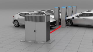
Featured image used courtesy of Adobe Stock