Facebook
 Google
 GitHub
 Linkedin
Designing Electronics to Pass the EMC Test Part 2
Part 1 discussed the conductive emission loop during a typical CE test. Part 2 will examine how to use this information to reduce the emission at lower frequencies.
Part 1 began with a discussion of conductive emission, and we saw the first example of the CM (Common Mode) emission path. We've noticed that from the EUT (Equipment Under Test) some RF gets coupled in the nearby (vertical and horizontal) plates, and the signal returns to the EUT as common-mode noise. We also see that a spectrum analyzer is connected to a LISN to measure each line's conductive emission (peak and quasi-peak).
Part 2 will examine this in more detail and discuss a few ways to reduce conductive emission. We will not go into theoretical analysis, but some analysis will be needed to make these series easy to understand. I will keep the discussion as simple as possible.
Understanding the Common Mode Noise Path
Part 1 described the Common mode loop in a typical EMC test scenario. Understanding this is fundamental since it will give you a tool to solve this problem. This path will be slightly different on every design, but once identified, you’ll have all the tools needed to solve it.
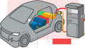
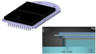
Let’s start with an example. In Figure 1, we have a DC/DC converter with a MOS switch connected to a heatsink. The MOS is connected to the heating using poor insulation material. In cases like this, the heatsink, maybe the cause of both Conductive Emission and Radiated Emission. But how? If you imagine a parasitic capacitor between the heatsink and the earthed (vertical) plate even with just a 20 pF parasitic capacitor, you may create a CM loop as shown in the diagram below.

Figure 1. A common mode current loop due to a high parasitic capacitor. Image used courtesy of Francesco Poderico
Can you see it? In this simple example, the heatsink is the source of a CM loop. Since we know the source, we can fix it. We can reduce the emission drastically, and there are many ways to do it.
For example, if it is possible to connect the body of the heatsink to the earth (this is not always possible, we change the CM loop from what we had earlier in Figure 1 to what we have below:

Figure 2. The CM loop is now very small since we have drastically reduced the effect of the parasitic capacitor. Image used courtesy of Francesco Poderico
Can you see it now? The CM current is not crossing the LISN, so we don’t have CE emission.
But what if we can’t do this? What if we can’t connect the heatsink to earth?
We have another way to modify the loop, for example, by using a shielded cable and connecting the cable to earth.

Figure 3. CM current bypassing LISN. Image used courtesy of Francesco Poderico
Can you see now how a shielded cable modifies the CM loop? We are “helping” the CM current to “bypass” the LISN.
You may say, ok, but shielded cables are too expensive. Do we have another way? Yes, we have other ways. The most common? The use of a common mode choke.
There are three main parameters needed to select the right CM choke:
1. maximum current allowed by the choke
2. expected emission graph
3. maximum attenuation
Maximum Current Allowed by the Choke
Let’s start from the current. In my design, I select the choke to allow the current to be at least 2 or 3 times the maximum expected from the EUT (e.g., if the EUT requires 1 A, I select a choke of 2 or 3 A). I do this to avoid degradation of the magnetic property of the filter.
Expected Emission Graph
In a lower frequency range domain (150 kHz - 30 MHz), most emissions are due to the DC/DC (or AC/DC) converter. These components usually switch around a few MHz or less. And, therefore, most of the expected emissions will be harmonics of the fundamental. So, for example, if we have only one DCDC converter that switches at 1 MHz, I expect to see most of the emissions at 1 MHz, 3 MHz, 5 MH and so on. (In a different article I will discuss how to fight even harmonics without using a CM choke.)
So, the key part is that our CM choke needs to be able to filter from 1 MHz up to 30 MHz at least, and not 150 kHz to 30 MHz.
Maximum Attenuation
Finally, we must decide the maximum attenuation we want in the frequency range of 1MHz to 30 MHz. As we have seen earlier, we don’t have real control of the parasitic capacitor, it could be around 20 pF, but it could be even less than that. We don’t know until we test the unit. I set the attenuation based on my experience with similar projects, for example, 30 dB. Once I have all these three parameters, I can finally go to a choke manufacturer and look at their insertion loss graphs. Most CM chokes manufacturers these days provide at least two graphs, one for the CM insertion loss and one for the DM (Differential Mode ) insertion loss. Those graphs are taken with measurements made from a LISN perspective, so when we add this to the power line, we should expect a similar attenuation. We are only interested in the CM insertion loss.
In the next article, I will dig into more detail, discussing simulating the CM choke with LTSpice and why and how to add X and Y capacitors Cx and Cy in your design and fight even harmonics on a DC/DC converter.
Featured image used courtesy of Pixabay