 Facebook
 Google
 GitHub
 Linkedin
Characterizing High-voltage Inductors and Magnetic Material via Triangular Flux Excitation
Measuring power inductors to obtain real-life, application-relevant data is a challenge. The challenge further increases when using high voltages, such as in offline applications like PFC, electric vehicle inverters, and fast-chargers.
DC losses are relatively easy to predict when the operating temperature and DC resistance are known. But to what extent are losses caused by the AC component of the current? How do these AC losses contribute to self-heating? Does the applied voltage cause other issues that impact reliability and lifetime?
These questions can only be answered when measurement data is available. Generating such data, in turn, requires a system that can apply real-life switching waveforms. high-voltage Madmix is the measurement system capable of characterizing such power inductors.
Figure 1 below shows the hardware of the high-voltage Madmix equipment, a software-controlled, fully-automated testbench for power inductors. A closeable cavity houses the inductor under test (LUT), protecting the environment and user from high voltages and EMI.
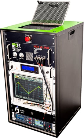
Figure 1. The high-voltage Madmix equipment. Image used courtesy of Bodo’s Power Systems [PDF]
Principle of High-voltage Madmix
The principle of operation is shown in Figure 2. It consists of a full-bridge DC/DC converter, where the inductor L is the device under test (LUT).

Figure 2. The HIGH-VOLTAGE MADMIX principle. Image used courtesy of Bodo’s Power Systems [PDF]
The LUT is subjected to a hard-switched, square-wave voltage which results in a triangular current and hence magnetic flux. The amplitude of the ripple current depends on the inductance, source voltage, frequency, and duty cycle according to the equation:
\[Irip=\frac{2\cdot V_{source}\cdot\delta(1-\delta)}{f\cdot L}\]
Where Vsource is the voltage source, δ is the duty cycle, f is the switching frequency, and L is the inductance of the inductor under test.
In normal operation, a DC bias voltage is built across the series capacitor when the duty cycle is lower or higher than 50%:
\[V_{DC}=V_{source}(2\delta-1)\]
As a result, the inductor may see a voltage higher that the supply voltage according to:
\[max(V_{L})=V_{source}+abs(V_{C})\]
where VL is the voltage across the LUT and VC is the voltage experienced by the series capacitor.
By measuring the voltage over and current through the LUT in a very accurate fashion and by using a high-bandwidth, high-resolution digital oscilloscope, various parameters of the LUT can be revealed. Key parameters include the inductance, total AC losses, core loss, winding loss, saturation current, and core breakdown voltage. As an example, the total AC losses are determined by calculating the integral of the LUT voltage and current and averaging them over multiple periods for higher accuracy.
\[P_{ac}=\frac{1}{T}\int^{T}_{0}i(t)v(t)d(t)\]
Key Specifications
The high-voltage Madmix uses state-of-the-art GaN switching technology and in-house developed drivers to enable switching the LUT with the following parameters:
- Voltage range across the inductor: 50 V 800 V
- Ripple current through the inductor: 50 mA-60 Aptp
- Frequency: 10 kHz-2 MHz
- Duty-cycle: 50%-95%
- Ambient temperature: -60°C-225°C
Very fast voltage transients up to 60V/ns are generated in this way, resembling state-of-the-art wide-bandgap applications, as shown in Figure 3.
The above parameters allow for stressing even large inductors up to their limits. An example is a 75 µH, 150 A-rated inductor, weighing about 3kg. Switching this part at 85 kHz, 500 V, and 40 Aptp yields an AC power loss of 140 W. This significant AC power loss is enough to reach a surface temperature of the inductor case of over 100°C in under 5 minutes, where the inductor had not yet reached a thermal steady state.
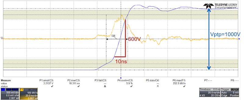
Figure 3. A real-life example of the fast switching transients that are used in high-voltage Madmix, up to 60V/ns. Image used courtesy of Bodo’s Power Systems [PDF]
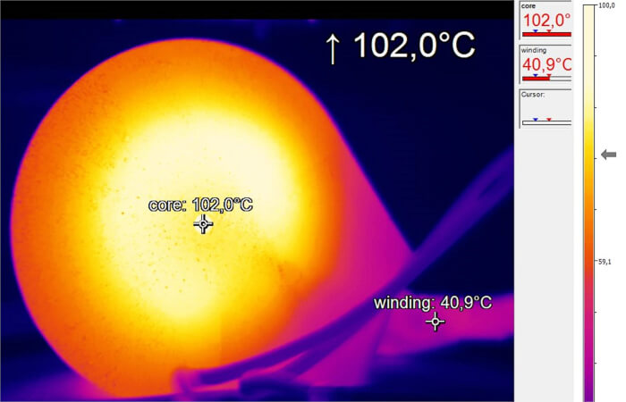
Figure 4. A 75µH, 150A rated inductor heated to 102°C in under 5 minutes by switching with the high-voltage Madmix equipment at 85 kHz, 500 V, and 40 Aptp. Image used courtesy of Bodo’s Power Systems [PDF]
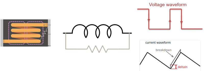
Figure 5. Inductor under core breakdown visualized by a leakage resistor to the inductor terminal (left) translated to an electrical equivalent model (middle) and the step effect visible on the triangular current (right). Image used courtesy of Bodo’s Power Systems [PDF]
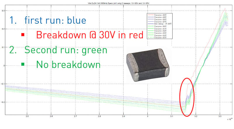
Figure 6. A real-life measurement showing a step in the LUT current from 30 V onward, indicating core breakdown. Image used courtesy of Bodo’s Power Systems [PDF]
Core Breakdown Voltage
An effect that is until today little known and understood is the breakdown of the inductor magnetic core as a result of the induced voltage differences within it. Indeed, under certain circumstances, the magnetic core may start to conduct current. This effect can be modeled by imagining a parallel “leakage resistor” across the terminal of the inductor. As a result, when excited under triangular flux, a step in the current waveform starts to show. This is depicted in Figure 5.
The high-voltage Madmix is able to reproduce this core breakdown effect by applying hard switching while an incremental voltage is applied to the inductor to detect the moment of breakdown. An example of such a measurement is shown in Figure 6. The current through the LUT starts to show a distinct step response from a certain voltage onwards, 30V in this case. Clearly, this is crucial information for both manufacturers and end-users.
Added Value
The high-voltage Madmix measurement system allows for performing an accurate prediction of the efficiency and overall performance of power inductor components in a wide range of growing applications like EV inverters, fast chargers, PFC, and more. This way, the performance of various commercial inductors and new inductor designs can be determined beforehand. high-voltage Madmix provides a clear insight into the important trade-off in designs, specifically cost, size, efficiency, and overall performance. Furthermore, in some niche applications, there is often no standard off-the-shelf inductor that fulfills the application requirements. In such a case, HIGH-VOLTAGE MADMIX allows the prototyping of power inductors with specific form factors and large temperature ranges (up to 225°C). Additional capabilities such as core breakdown voltage detection bring deep insights to power inductor manufacturers and researchers alike.
This article originally appeared in Bodo’s Power Systems [PDF] magazine.


Very nice article, knowledge infected