Facebook
 Google
 GitHub
 Linkedin
Magnetized Simulation of Customized Permanent Magnetic Objects
This article discusses the magnetization of a virgin magnetic material into a permanent magnet in magnetic solver AMPERES.
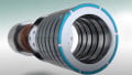
In the model, a piece of virgin magnetic material in the desired shape was exposed to highly impressed magnetic fields produced by the magnetic chargers. Different regions were exposed to different impressed magnetic fields simultaneously to get a customized pattern of magnetic orientation. Images show a semicircular ring magnetized in 6 alternatively reversing magnetization directions oriented along its axis. The angular stretch of each magnetization portion is 300. Accordingly, a magnetic charger having 6 sets of coils with alternatingly changing senses of current flow is modeled.
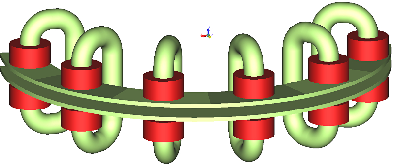
Figure 1. Magnetizing Charger. Image used courtesy of Bodo’s Power Systems [PDF]
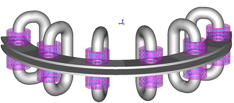
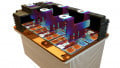
Figure 2. Current sense. Image used courtesy of Bodo’s Power Systems [PDF]
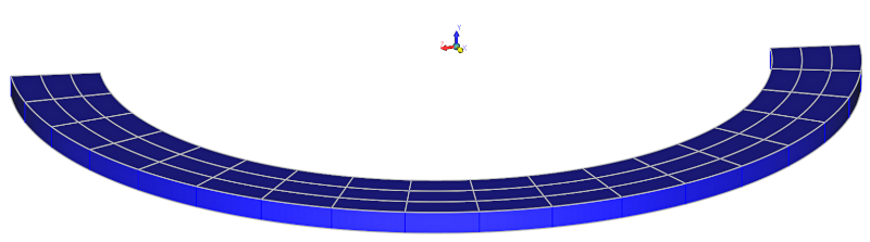
Figure 3. Semicircular ring to be magnetized. Image used courtesy of Bodo’s Power Systems [PDF]
The virgin piece of the semicircular magnetic ring was sandwiched between the charger plates, and appropriate material was assigned to the model. This model was discretized and solved by selecting the command “Magnetize” in AMPERES. Once magnetization was done, the geometry related to the magnetic charger was deleted and the appropriate permanent magnetic material property was assigned to the semicircular disk. This model was solved by hitting “Run Solver” in AMPERES to determine the magnetic fields produced by the magnetized ring.
This simulation involved two important actions. First, the material to be magnetized was divided into many smaller volumes because the higher the number of divisions, the better was the accuracy. However, the number should not be more than a required number. In this example, the semicircular ring was divided into 6 equal angular portions and each angular portion was subdivided into 9 smaller volumes. In total, the semicircular ring was divided into 54 (=6X9) smaller volumes. The reason for dividing the magnetizing piece into smaller volumes was that AMPERES calculated the magnetic flux density vector (B) at the geometric center of each smaller volume and magnetized it in the direction of B vector. The program will also assign an appropriate new permanent magnetic material to each smaller volume.
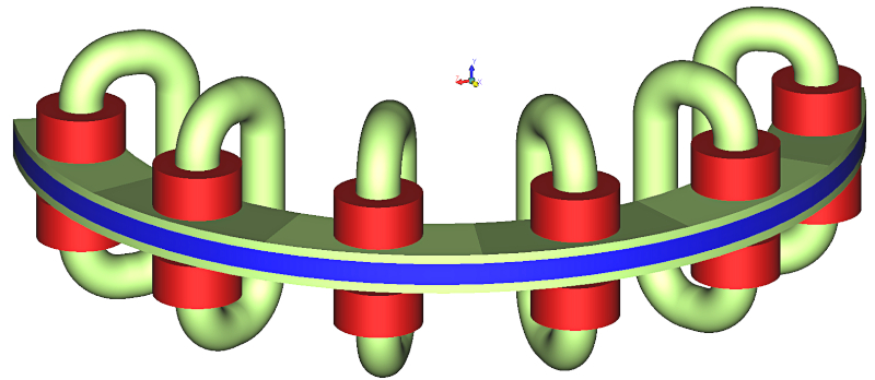
Figure 4. Semicircular ring sandwiched between the plates the magnetizing charger. Image used courtesy of Bodo’s Power Systems [PDF]
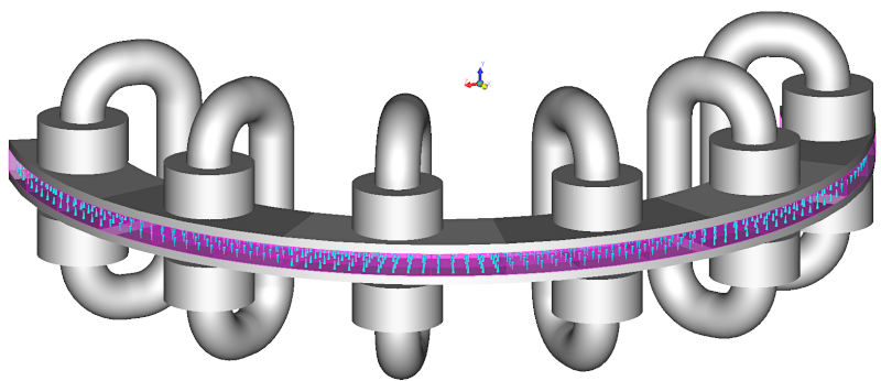
Figure 5. Permanent magnet directions of discretized volumes of the semicircular ring after magnetized. Image used courtesy of Bodo’s Power Systems [PDF]
The demagnetization curve of this new material which would be a scaled down version of the demagnetization curve of the permanent magnetic material that was assigned to the virgin material. The scaling factor is the ratio of the B field value at the geometric center of the smaller volume and the user specified minimum B field required to magnetize the virgin material to the fullest strength. Fullest strength we mean, the permanent magnet will have the vendor specified demagnetization curve after the magnetization.
It is important to note that the magnetic material property of the virgin piece is the same as that of the permanently magnetized piece. For the virgin piece, the magnetic material can be a linear material with a constant relative permeability, or a nonlinear material specified by a nonlinear B-H curve confined to the second quadrant only.
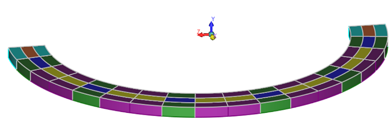
Figure 6. Minor permanent magnetic materials assigned to discretized volumes after magnetized. Image used courtesy of Bodo’s Power Systems [PDF]
After the magnetization is done in AMPERES, program assigns different minor permanent magnetic materials which are the scaled down versions of the permanent magnetic material initially assigned. The B-field results shown in Figures 7 and 8 are with the minor permanent magnet materials, whereas the same shown in Figures 9 and 10 are with the permanent magnet material initially assigned. From these results, you can see the effect of using minor magnetic materials which were calculated by AMPERES.
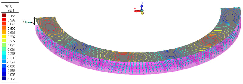
Figure 7. Magnetic charger deleted. Contours of the Y component of magnetic flux density vector B on a surface 10mm above the magnetized semicircular ring. Image used courtesy of Bodo’s Power Systems [PDF]
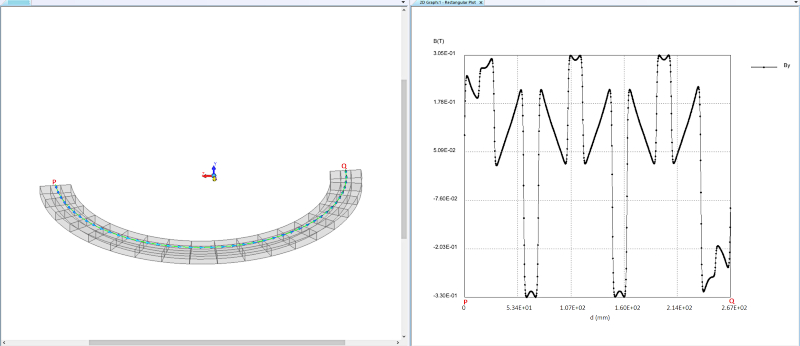
Figure 8. Variation the Y component of magnetic flux density B along a semicircular arc 1mm above the magnetized ring. Image used courtesy of Bodo’s Power Systems [PDF]
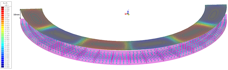
Figure 9. To all small volumes initial permanent magnet material is assigned. Contours of the Y component of magnetic flux density vector B on a surface 10mm above the magnetized semicircular ring. Image used courtesy of Bodo’s Power Systems [PDF]
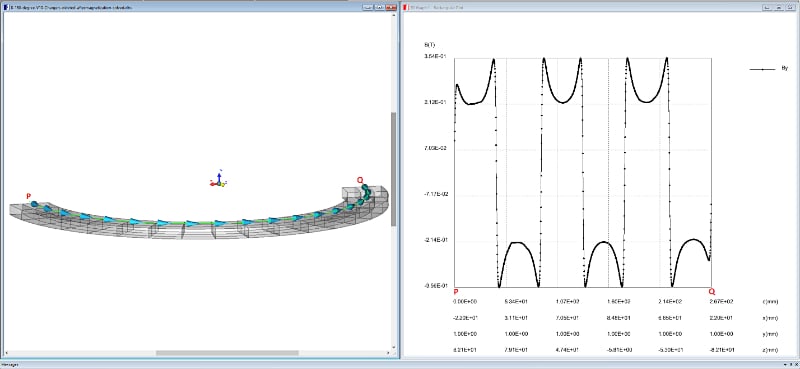
Figure 10. To all small volumes initial permanent magnet material is assigned. Variation the Y component of magnetic flux density B along a semicircular arc 1mm above the magnetized ring. Image used courtesy of Bodo’s Power Systems [PDF]
This article originally appeared in Bodo’s Power Systems [PDF] magazine.