Facebook
 Google
 GitHub
 Linkedin
How to Increase Efficiency and Mitigate Power Loss in Buck Converters
Determining the best match between an inductor and an IC is paramount to achieving the best performance in terms of PCB space, as well as thermal and cost-efficiency.
Today’s highly developed power ICs require superior power inductors. Building a standard power supply with common footprints can help reduce design time and production costs. Determining the best match between an inductor and an IC is paramount to achieving the best performance in terms of PCB space, as well as thermal and cost-efficiency.
Let’s explore which parameters are most important when designing a buck (step-down) converter, and how to pair it with the best inductor available. We will also learn how to calculate basic parameters and explain some of the requirements for both switch-mode power ICs and inductors, including ripple current, inductance (L), saturation current (ISAT), and rated current (IR).
Today’s Electronics Landscape Over the past 10 years, consumers have grown to expect that technology will make their lives easier. At the same time, the amount of electronic items in the average home has increased. Ever-increasing options for connectivity and electronics mean these devices must become more efficient to remain competitive. For power supply designers, the best way to support this consumer shift in electronics usage is to convert voltages from the input to the necessary supply rails with a step-down converter utilizing high-performance parts.
The most common power supply topology is the buck or step-down converter. The main components for these topologies are input and output capacitors, switches (e.g. MOSFETs), and an inductor. The goal of these devices is to regulate the output voltage. High-side and low-side MOSFETs come in handy when they are combined with a regulator, and form an integrated step-down regulator IC.
Selecting a suitable IC with the best inductor does not have to be a significant challenge. Taking care of a few design parameters is the key to successfully choosing an inductor that works well with a buck converter, and to avoiding power losses and increasing efficiency.

Figure 1: Basic Buck Converter Schematic
Fundamentals of Buck Converter Power Losses and Efficiency A block diagram of a buck converter and its basic parts makes it apparent which components contribute to efficiency, and which parameters should be considered (see Figure 1).
When breaking down the efficiency and power loss of a buck converter, we can see that the biggest impacts on power loss and efficiency are the MOSFETs and the inductor. The quiescent current and programming resistors are not notable contributors (see Figure 2).

Figure 2: Efficiency Chart of the MPQ4572 Buck Converter with the MPL-AL6060-150 15μH Inductor

Figure 3: Efficiency Breakdown of a Buck Regulator
Figure 3 shows an efficiency breakdown of a 24V to 5V buck converter with a 2A load. While the inductor and MOSFETs have 870mW of power loss, quiescent power consumption adds just 900μW to the total sum. To achieve the highest efficiency and avoid wasting energy, we must ensure that state-of-the-art switching elements are coupled with high-performance inductors.
Inductance (L)
As a rule of thumb, it is usually recommended to start a converter design with a 30% to 40% ripple current. This leads to a nominal inductance (L), calculated with Equation (1):
Where DC is the duty cycle of the converter, VOUT is the output voltage, fSW is the switching frequency, and ΔIL is the ripple current.
For this example, the input voltage is 24V, the output voltage is 5V, the ripple current is 800mA (average 2A load), and the switching frequency is 500kHz. With these numbers, we can calculate the typical inductance to be 9.89μH.
Ripple Current (ΔIL)
Ripple current (ΔIL) is the amount of low-frequency AC current that is superimposed onto the average load current and flows through the main power inductor to charge the output capacitor (COUT). The ripple current can be estimated with Equation (2):

Figure 4: Ripple Current on Average Load Current

Figure 5: Inductor Current (Blue) and Switch Node Voltage (Yellow) of a 24V Buck Converter
Figure 4 shows important design parameters, including peak current (IPEAK) and average current (IAVG). This average current is the intended load current of our system, and is connected to the buck converter’s output. Half the ripple current (ΔIL) is added to the average load current, forming the peak current. For a successful and highly efficient buck converter design, it is essential that the inductor’s saturation current (ISAT) exceeds the peak current.
Figure 5 shows an example of an optimized 24V to 5V step-down converter, utilizing the MPQ4572 from MPS together with a 15μH inductor (MPL-AL6060-150). The ripple current oscillates around a 2A load current with a perfect triangular waveform.
Saturation Current (ISAT) Due to the physical properties of the ferromagnetic material used in modern inductors, a higher number of turns and inductance (L) results in a lower the saturation current (ISAT). Figure 6 shows a typical ISAT graph. From this graph, we can expect an effective inductance of 13μH at a 2A load current.
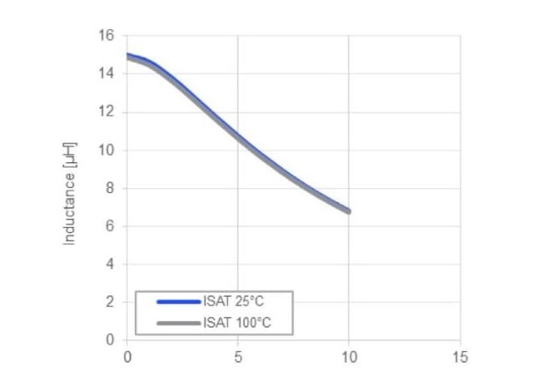
Figure 6: Saturation Current (ISAT) as a Function of the Inductor Current (IL)

Figure 7: Inductor Current (Blue) and Switch-Node Voltage (Yellow) with Too Low Saturation Current
As power supply designers, it is critical to keep in mind that inductance decreases when the current flowing through the inductor increases. Increasing temperatures decrease the effective inductance. Depending on the technology, structure, and materials used in the inductor, the curve of the saturation current can be stable up to several amperes.
Because high-efficiency inductors have a soft saturation and buck converter, ICs have protection features such as peak current limiting. This means there is no way to choose the wrong inductor. Even with an exceedingly high or low inductance, we will still see reasonable results. However, it is important to have enough margin on the saturation current, as an insufficient margin can lead to a low-efficiency system. A lower saturation current can contribute to sharp spikes on the inductor current (see Figure 7).
Rated Current (IR) and DC Resistance (RDC) Another important parameter to consider is the rated current (IR). Remember, as inductance increases, the rated current (IR) decreases. Moving forward, we can directly use the average load current as an estimate for the effective temperature rise (ΔT).
The temperature rise is directly related to self-heating because of DC losses inside the copper windings. This means that the lower the DC resistance, the better the self-heating, and the higher the inductor’s rated current (IR).
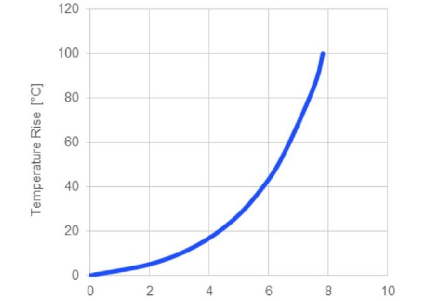
Figure 8: Rated Current Chart
The diameter of the enameled copper wire, which forms the coil of an inductor, is smaller in smaller package sizes. This leads to higher DC resistance, DC loss, and lower IR. Choosing a good compromise between the package size and rated current is important for a successful buck converter design. As a rule of thumb, a temperature rise of 20°C to 30°C for average operating conditions is a solid starting point (see Figure 8). Having exceptionally small components on the PCB is also important in terms of EMC, as hot loops can become smaller.
Matching the Inductor and Buck Regulator for Optimal Efficiency Now that we have gone through the fundamentals, finding the optimal efficiency of a buck converter means that we need to choose a regulator IC and an inductor that match one another’s performance. If we disregard the inductor’s AC losses and the MOSFETs’ transition losses, we can focus on DC power losses.
The power loss (PLOSS) of any conductor can be calculated with Equation (3):
The conduction losses from our switching MOSFETs don’t always add up for the whole switching period since MOSFETs have an on and off time. While the high-side MOSFET (HS-FET) is on, it gives us a power loss multiplied with the duty cycle (DC). By comparing the DC resistance (RDC) of the inductor with the RDS(ON) of our MOSFETs, we can use the fraction of the RDS(ON) for matching. Both terms (RDC) and (DC x RDS(ON)) should be close to one another. They don’t need to be perfectly equal, but we can see the optimal efficiency with close terms (within mΩ).
For example, for a 24V to 5V conversion, there is a duty cycle of VOUT / VIN = 0.208, meaning the HS-FET conducts the inductor current only 20.8% of the time. This means the conduction loss only adds up to 20.8% of the total conduction losses. However, the low-side MOSFET (LS-FET) is conducting the inductor current at 79.2%, which is on most of the time. This why most modern buck regulators have differently scaled MOSFET switches.
To minimize losses and achieve an efficient compromise between size, performance, and cost, first match the DC resistance of the inductor with the ratio of the MOSFETs’ RDS(ON).
Since modern buck converters have switch on resistances that range from tens to hundreds of mΩ, the best performance can be matched with small and highly conductive power inductors that utilize round or flat copper wires together with a molded ferrite compound.
Conclusion
Matching the right inductor and buck converter can be a challenge with the vast number of different inductors on the market. Even if we make compromises between size, efficiency, and cost, there is always a best choice of inductors that meet the technical and environmental requirements of our final application.
Both modern buck regulator ICs and molded power inductors are available with DC and conduction resistances in the tens of mΩ range. Making sure that all of the resistances are in the same range helps achieve an optimal compromise between size and efficiency. Larger package inductors and MOSFETs typically help reduce power loss. However, at a certain size, cost and B space increase rapidly with no significant performance boost toward this goal. Therefore, aiming at the necessary saturation current (ISAT), rated current (IR), resistance (RDC), and ON-resistance (RDS(ON)) is a fast and easy way to achieve outstanding performance with a reasonable effort to create a perfect match of power inductors with buck (step-down) converters.
About the Author
Samuel Babijak is a field applications engineer at Monolithic Power Systems.