 Facebook
 Google
 GitHub
 Linkedin
Difference Between A Capacitor And Inductor
Analysis of AC Systems
Capacitors
A capacitor exhibits a relatively large amount of capacitance. Capacitance, which is measured in farads, is the ability to store energy in the form of an electric field. Capacitance exists whenever two conductors are separated by an insulating material; in this context, the insulating material is called the dielectric.
In many cases, this capacitance is unintentional and undesirable. When we actually want to add capacitance to a circuit, we use a capacitor, which is a device that provides high capacitance in a convenient form factor. The most straightforward physical design for a capacitor is the parallel-plate structure, i.e., two conductive plates separated by a thin dielectric.
When a capacitor is first connected to a voltage source, the voltage across the capacitor gradually increases as the current supplied by the source charges the capacitor. During this time, the current in the circuit is gradually decreasing. Eventually, the capacitor will be fully charged, at which point it behaves like an open circuit: no current will flow until something changes and allows the capacitor to discharge.
The RC Circuit
When we connect a resistor and a capacitor in series, we have something called an RC circuit.
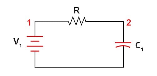
Figure 1. An RC circuit connected to a battery.
This simple network is surprisingly important and appears frequently in professional circuit design. For example, when connected to an AC signal, it becomes a low-pass filter.
When a capacitor is being charged, its voltage doesn’t increase linearly. Rather, a plot of capacitor voltage vs. time has an exponential shape. The current through the capacitor is also governed by an exponential relationship.
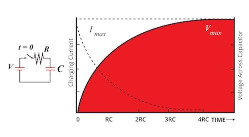
Figure 2. After the switch is closed, the voltage across the capacitor exponentially increases and the current through the capacitor exponentially decreases.
Notice how the current changes in a way that is opposite to how the voltage changes. In a purely resistive circuit, voltage and current follow each other: if voltage increases, current increases; if current increases, voltage increases. Now that a capacitor has been inserted into the current path, the situation is different—voltage increases as current decreases.
The RC Time Constant
The length of time required for the capacitor to reach a certain voltage is related to the capacitance (C) of the capacitor and the resistance (R) of the resistor. Higher resistance or higher capacitance will make the charging process occur more slowly.
If we multiply resistance by capacitance, we have the RC time constant. This quantity provides a convenient way to discuss the temporal characteristics of an RC circuit:
- After charging for the length of time corresponding to one RC time constant, the capacitor will have a voltage that is about 63% of the supply voltage. (When a capacitor is discharging, the voltage after one RC time constant will be about 100% – 63% = 37% of the supply voltage.)
- After a capacitor has charged for the length of time corresponding to five RC time constants, its voltage is approximately 99% of the supply voltage. According to the mathematical formula that expresses the relationship between voltage and time, the capacitor never charges to 100% of the supply voltage. In practice, though, we can say that the capacitor is fully charged after five RC time constants.
The following plot conveys the mathematical relationship between charging behavior and the RC time constant. The percentages are equivalent to Vcapacitor/Vsource, i.e., they indicate the percentage of the supply voltage that is present across the capacitor at different moments during the charging process.
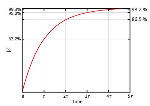
Figure 3. The mathematical relationship between charging behavior and the RC time constant
Inductors
These sections on inductors will be shorter than the sections on capacitors. Why? Because these two components are “mirror images” of each other, and consequently the concepts discussed above are relevant also to inductors.
Capacitance, as we now know, is the ability to store energy in the form of an electric field. Inductance, which is measured in henries and denoted by the letter L, is the ability to store energy in the form of a magnetic field.
An inductor is a conductive component that is designed to generate a strong magnetic field, because a stronger magnetic field corresponds to higher inductance. The fundamental physical structure for an inductor is a coil of wire.
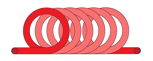
Figure 4. The fundamental physical structure for an inductor.
This structure is used because a current-carrying wire generates a circular magnetic field (see Figure 5), and placing multiple loops side by side leads to a concentrated magnetic field inside the coil (see Figure 6).
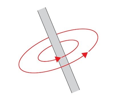
Figure 5. Current-carrying wires generate a circular magnetic field.
The device shown in Figure 6 would be called an air-core inductor because there is no magnetic material inside the coil of wire. Inductors are commonly constructed using magnetic core materials that increase the device’s inductance, though air-core inductors are preferred in certain applications.
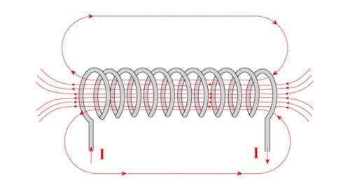
Figure 6. An air-core inductor.
Electrical Behavior of Inductors
The basic functionality of an inductor is equivalent to that of a capacitor if you swap current and voltage. The following table will help you to understand inductors based on what you already know about capacitors:
| Capacitor | Inductor |
| stores energy in an electric field | stores energy in a magnetic field |
| initially has zero voltage (in other words, initially looks like a short circuit) | initially has zero current (in other words, initially looks like an open circuit) |
| has a voltage drop that increases exponentially after a voltage source is connected | has current flow that increases exponentially after a voltage source is connected |
| has current flow that decreases exponentially during the charging process | has a voltage drop that decreases exponentially during the charging process |
| charges and discharges according to the duration equal to resistance times capacitance, i.e., the RC time constant | charges and discharges according to the duration equal to resistance times inductance, i.e., the RL time constant |
Resisting Change
You should be aware of two statements that are frequently used when discussing these two components:
- Capacitors resist changes in voltage.
- Inductors resist changes in current.
These concepts can help you to understand how an inductor or capacitor will respond to certain circuit conditions. Capacitors and inductors “resist” change because they naturally compensate for change using their stored energy. For example, if the supply voltage connected to an RC circuit is suddenly shorted to ground, the voltage across the capacitor doesn’t immediately drop to zero. Instead, the voltage gradually decreases as the stored energy is converted into electric current.
Capacitors and Inductors Review
This page has provided a brief introduction to inductors and capacitors. These fundamental components appear again and again in all types of circuit design, and it’s very important to gradually acquire a thorough understanding of their behavior and characteristics.
In the next page, we’ll continue our study of power in the context of AC systems.
Thanks for supporting me about increasing my knowledge