Facebook
 Google
 GitHub
 Linkedin
Distribution Transformers and Voltage Regulation—Part 1: Introduction
Learn how distribution transformers bridge medium-voltage feeders and end-use equipment, ensuring stable voltage through strategic placement, loading, and adherence to thermal and ANSI/NEMA standards.
Distribution transformers sit at the practical interface between medium-voltage (MV) feeders and utilization voltages, shaping the voltage profile seen by end-use equipment and influencing both technical performance and operating cost. Their placement, loading, and control features determine whether voltage stays within accepted limits under daily cycling and contingency events.
This article reviews how distribution transformers step MV to service levels, how placement affects feeder voltage and losses, how loading varies by customer mix, and how nameplate versus thermal limits guide short-term and sustained loading decisions.
Purpose and Standard Utilization Levels
The primary role of a distribution transformer is stepping MV—commonly 11–33 kV in many systems—down to standardized utilization voltages. In North America, service and utilization voltage limits are defined by ANSI/NEMA C84.1, with Range A intended for normal operation and Range B for infrequent, short-duration excursions. Typical secondary systems include 120/240 V single-phase, 208Y/120 V three-phase wye, and 480Y/277 V three-phase wye. Target service limits for these systems are specified in C84.1 and widely adopted by utilities.
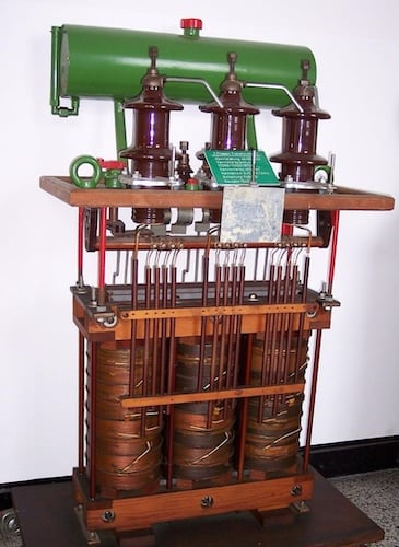
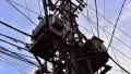
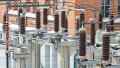
Figure 1. Three-phase distribution transformer. Image used courtesy of Wikipedia.
In IEC regions, 230/400 V is the standardized low-voltage level for three-phase four‑wire systems, formalized in IEC 60038, which harmonized prior 220/380 V and 240/415 V practices. This global alignment simplifies equipment design and helps clarify acceptable service ranges across geographies.
| System Level | Common Nominal Voltages | Typical Configuration | Region |
| Primary (MV) | 12.47 kV, 13.2 kV, 24.94 kV, 34.5 kV |
3-phase wye | US feeder voltages (selection varies by utility) |
| Secondary (LV) | 120/240 V; 208Y/120 V; 480Y/277 V; 400/230 V | Single-phase; 3-phase wye |
120/240, 208Y/120, 480Y/277 common in North America; 400/230 common in IEC regions |
Table 1. Typical voltage levels used in distribution practice
The preferred MV nominal voltages above are representative of common US practice documented for rural and suburban systems, together with recommended end-of-line and utilization-point limits that align with C84.1.
Placement in the Network
Transformer location along a feeder directly affects voltage quality and losses:
- End‑of‑feeder placement exposes the transformer to the cumulative upstream voltage drop and voltage variability from feeder loading. Under peak conditions, primary voltage at the end can be the limiting factor in keeping secondary service within Range A, especially where conductor impedances and loading profiles create significant drop. Feeder voltage regulators and line‑drop compensation (LDC) settings are typically applied to ensure end‑of‑line service remains inside C84.1 limits.
- Mid‑feeder siting can improve voltage headroom by reducing primary drop to the transformer and shortening secondary/service runs to nearby loads, which reduces I²R losses on the low‑voltage side. Strategic use of regulators and capacitors—at substations and along the feeder—coordinates with transformer taps to maintain an acceptable voltage spread at the substation bus, transformer primary, meter socket, and utilization point. Guidance from utility engineering practice describes allowable spreads (on a 120‑V base) and how to allocate them across feeder, transformer, secondary, and service segments to meet Range A in normal operation.
Placement decisions also reflect the interaction between regulator bandwidth, LDC R‑X settings, and transformer tap positions. De‑energized no‑load taps (DETCs) on distribution transformers allow shifting the ratio in fixed steps—commonly a few ±2.5% increments—so the base profile set by regulators can deliver secondary voltages inside the target band over the daily load cycle without constant intervention.
Load Characteristics
Distribution transformers serve widely varying load compositions, and their voltage‑regulation behavior is shaped by load diversity, daily coincidence, and power factor.
- Residential loading tends to peak in the late afternoon and evening, with a relatively high diversity factor across individual homes. The LV circuits often comprise long secondary/service runs where conductor loss and voltage drop are nontrivial, so coordination among feeder regulator setpoints, transformer taps, and secondary conductor sizing is essential to keep service points within Range A under seasonal peaks. Utilities often reference recommended spreads from planning guides to partition allowable drop among feeder and secondary segments.
- Commercial loading generally peaks during daytime business hours and includes substantial motor loads (HVAC, elevators) and lighting. Nonlinear office and retail equipment can introduce current harmonics. Transformer capability under non-sinusoidal loading is addressed by IEEE C57.110, which provides calculation methods and application guidance for evaluating existing units and specifying new ones. Where harmonic currents are material, K‑factor or harmonic‑mitigating designs and careful neutral sizing may be appropriate to contain heating and voltage distortion.
- Mixed loading smooths the feeder load factor but can create local constraints near load centers, where voltage support and thermal capability must be checked both for the feeder section and for the distribution transformer serving a dense cluster. Proper placement of capacitors and regulators, combined with transformer tap selection, balances day‑night peaks while meeting C84.1 Range A at the meter and within the equipment performance envelope at the utilization point.
Transformer Loading Concepts
Transformer nameplate rating provides the continuous base capability under standard reference conditions. Actual operating limits, however, depend on ambient temperature, load profile, and insulation system thermal response. Two practical concepts guide operating decisions:
- Diversified loading acknowledges that not all connected loads peak simultaneously. For pole‑top and pad‑mounted distribution units serving residential or mixed loads, diversified peak kVA can remain below the arithmetic sum of connected kVA. Planners leverage historical coincidence to right‑size units and feeders while still meeting service voltage criteria across the day; regulator setpoints and transformer taps provide the voltage cushion when diversity narrows during local events or extreme weather. Planning guides detail how allowable voltage drops are allocated to ensure Range A performance at the service point and utilization point.
- Short‑term overloading is bounded by winding hottest‑spot temperature and insulation aging. The IEEE loading guide for mineral‑oil‑immersed distribution transformers (IEEE C57.91) establishes the framework for calculating hottest‑spot temperature and relative aging rate, and it provides recommendations for loading above nameplate under specified ambient and pre‑loading conditions. A key reference point is the 110 °C hottest‑spot temperature associated with normal life; excursions above this level for limited durations are permitted if offset by cooler operation at other times, using the guide’s methodology to track cumulative loss‑of‑life.
Thermal time constants matter in real operation. During overloads, winding and duct oil temperatures rise faster than tank bulk oil, so the peak hottest‑spot temperature can occur after the load peak, affecting how long an overload can be sustained before protective action is required. IEEE C57.91 discusses this lag and its implications for short‑time emergency (STE) and long‑time emergency (LTE) ratings.
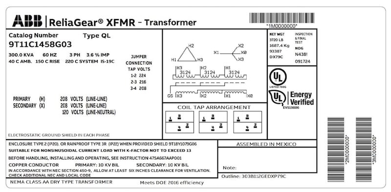
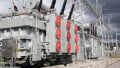
Figure 2. Transformer nameplate details. Image used courtesy of ABB.
Taps, Regulation Equipment, and Coordination
Distribution transformers typically use de‑energized taps for seasonal or planning adjustments, while on‑load tap‑changers are more commonly found on substation power transformers and line regulators. The broader regulation scheme relies on:
Substation and line voltage regulators with LDC to maintain end‑of‑line voltage targets despite feeder R‑X drop. Proper LDC settings subtract a calculated voltage drop (vectorially) from the sensed voltage to hold the remote load center within the desired band.
Capacitor banks, placed at substations and along the feeder, reduce reactive current and limit line drop, which improves voltage profile and reduces losses. Their interaction with regulator setpoints and transformer taps must be considered to avoid overvoltage under light load or backfeed conditions. Planning guidance emphasizes coordination of these devices so that transformer primaries remain within allowable ranges while secondaries meet Range A at service and utilization points.
General transformer construction and rating requirements—including tap capabilities and test codes—are defined in IEEE C57.12 for liquid-immersed distribution, power, and regulating transformers. These standards frame available tap ranges and how ratio changes relate to thermal capacity, ensuring voltage-regulation strategies remain consistent with transformer design limits.
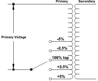
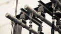
Figure 3. Transformer with four taps. Image used courtesy of Voltage Disturbance.
Practical Implications For Losses And Voltage Profile
Losses concentrate where current and conductor length are greatest. Locating transformers closer to load concentrations shortens LV runs and typically lowers secondary I²R loss. Conversely, minimizing the number of small transformers by moving capacity toward feeder ends can simplify asset counts but risks higher secondary losses and tighter primary voltage headroom.
Planning methodologies therefore allocate allowable voltage drops among feeder, transformer, secondary, and service segments, aiming to keep meter and utilization points within C84.1 Range A under normal conditions and to limit Range B excursions during contingencies.
Harmonic content from nonlinear loads increases winding and stray losses and can elevate neutral currents in multi‑wire systems. IEEE C57.110 provides procedures to determine capability under nonsinusoidal currents, supporting decisions on K‑factor designs, derating, or harmonic‑mitigating transformer applications so that thermal performance and voltage quality remain acceptable.
Shaping the Voltage Profile
Distribution transformers do more than reduce voltage; they actively shape the voltage profile delivered to end‑use equipment while balancing between feeder behavior, load composition, and thermal limits. Selecting appropriate secondary voltage standards, siting units along the feeder to balance voltage headroom and secondary losses, and matching transformer design to the harmonic and coincidence characteristics of the served load are all central to reliable performance.
Within those design decisions, operating limits depend on accepted service and utilization voltage ranges and on thermal guidance that permits temporary overloads when justified by ambient conditions and subsequent cool‑down. Effective coordination among substation regulators, line LDC settings, capacitor placement, and transformer taps keeps service within the desired band as load moves through the daily cycle.
Applying the accepted standards—C84.1 for voltage ratings and ranges, the IEEE loading guide for thermal capability, and IEEE requirements for tap functionality—provides a consistent framework for planning, operating, and upgrading distribution transformers in support of sound voltage regulation.