Facebook
 Google
 GitHub
 Linkedin
AI Server Hot-Plugging With Hot-Swap Controllers
This article features strategies for reliable and continuous operation in AI server data centers using hot-swap controllers.
This article is published by EEPower as part of an exclusive digital content partnership with Bodo’s Power Systems.
This is the age of 24/7 AI usage, where AI servers need to be always online. Their ever-growing power demand forced server architectures to transition from 12 V to 48 V, which reduced power losses by 16x, allowing greater power extraction with reduced cooling costs. An AI server rack computes the required data in an interruption-free operation and comprises multiple AI server blades that operate in parallel. Server blades, in turn, are composed of a power converter, an AI processor, network switches, and memory.

Image used courtesy of Adobe Stock
AI Servers and Hot-Plugging
Visualize parallel AI server blades as drawers of a filing cabinet: the back of the cabinet into which these drawers (server blades) wheel in is a 48 V live backplane, and the cabinet is the server rack. The blades are plugged into this backplane powered by the same source as the processors. If one blade fails, the load is shared by the others to keep the system running. Meanwhile, the faulty blades are replaced by plugging new blades into the live backplane without taking the entire system offline. This process is called “hot-plugging” or “hot-swapping.”
To avoid costly server downtimes or high replacement costs, which can exceed $9000/minute per Forbes, server blades must be protected against system-level failures due to voltage fluctuations or thermal variations, among other factors. This is where hot-swap controllers, as reliable protection solutions for AI servers, come into play.
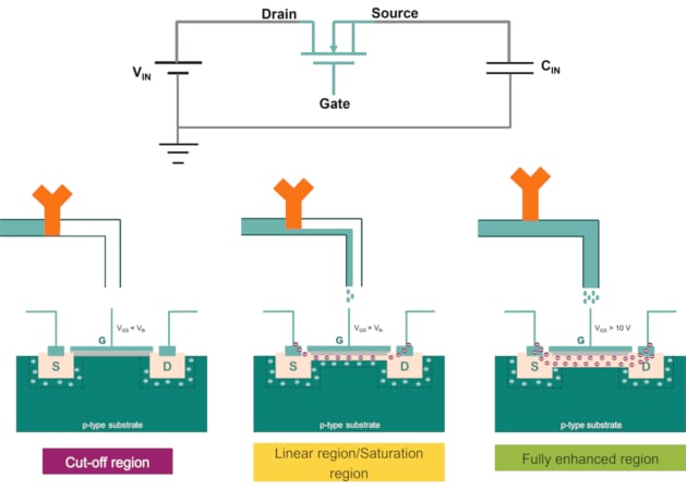
Figure 1. Capacitor inrush current analogy with a water reservoir example. Image used courtesy of Bodo’s Power Systems [PDF]
Hot-Plugging Events
Every hot-plugged server blade contains a capacitor for energy storage purposes and to filter out voltage ripple and high-frequency noise. At insertion of the server blade, the capacitor is discharged, acting as a short or low-impedance path from VIN to ground. Hotplugging a server blade at this moment creates a huge amount of inrush current for a short time. But it is strong enough to blow up the fuse or cause voltage dips in adjacent blades, triggering a system shutdown. The increasing power density originating from the growing power demands of AI servers also requires additional capacitance, making it critical to reduce this inrush current.
One technique to reduce inrush current is to increase the current path resistance by adding a series resistance between VIN and CIN. Increasing resistance to the power-path would cause a voltage drop, adding to I2R losses. Another technique utilizes negative temperature coefficient (NTC) thermistors, offering a high resistance before hot-plugging. Inrush current passing through NTCs of a room-temperature server blade generates heat from I2R losses, reducing the resistance. Thus, NTCs significantly reduce steady-state system losses. The resistances could be shunted using a switch/relay, which increases size, cost, and complexity. They are also unreliable when faulty blades need to be isolated.
Hot-Swap Controller Mechanism
Clearly, a solution is needed where the input current to the capacitor can be controlled during hot-plugging without causing voltage drops or power losses during normal operations.
Imagine the backplane as an infinite water reservoir and the input capacitor as an empty water tank. To control the water flowing from the reservoir to the tank, a control valve is added, without which the water flows into the tank at the maximum flow rate, just like the inrush current. In this analogy, the valve is a MOSFET, whose gate voltage determines the current flowing through it. When the MOSFET gate voltage is below Vth (turn-on threshold), it operates in the cut-off region without allowing current to flow through, blocking the current flow (inrush current) while inserting the blade into the backplane.
As VGS > VTH, a controlled current flows through the FET. Initially, the current depends on VGS while VDS is high, placing the MOSFET in the saturation region, where the current is constant as long as VGS is stable. As VGS increases, more current flows, charging the input capacitor and lowering VDS, transitioning the MOSFET into the ohmic region where the current depends on RDS(on).
For hot-swap applications, 100 V MOSFETs are common with typical RDS(on) values between 1.5 mΩ and 3.5 mΩ. Identical MOSFETs are paralleled to share current, reducing thermal stress by effectively lowering RDS(on) per FET.
A hot-swap controller controls the MOSFET gate voltage to regulate the capacitor current at startup. It also ensures that the MOSFET is not damaged, staying within its design limits defined by the safe operating area (SOA) curves found in the MOSFET’s datasheet.
Digital Hot-Swap Controllers
To keep up with the growing power demand, digital hot-swap controllers allow for programming of the FET’s SOA profiles to ensure that the FET always stays within its safe operating region and improve overall system reliability and lifetime. Its algorithm works as follows:
1. MOSFET SOA current profile from VDS = 80 V down to VDS = 1 V is programmed at the desired temperature
2. When hot-plugging, the FET’s VDS = VIN. The controller refers to an internal lookup table and sets the corresponding drain current as the target FET drain current
3. The controller ramps up VGS slowly and measures the current flowing through the FET, regulating it to maintain the programmed current level
4. As current flows, the capacitor CIN charges, increasing the VOUT and reducing VDS
5. Controller adjusts target regulation current as VDS decreases
6. Once CIN is fully charged, the inrush event ends; the controller signals the power converter “Power Good”
7. The power converter powers up the processor, bringing the server blade online
4 kW Hot-Swap
A 4 kW hot-swap solution with four OptiMOS 5 Linear FET 2 IPT017N10NM5LF2 FETs and an XDP XDP710-002 hot-swap controller is available from Infineon. The board operates from 40 V to 60 V, and the nominal load current is 4000 W = 100 A; thus, four FETs are operated in parallel after thermal calculations. The SOA profile of the FET at 95°C is programmed into the controller.
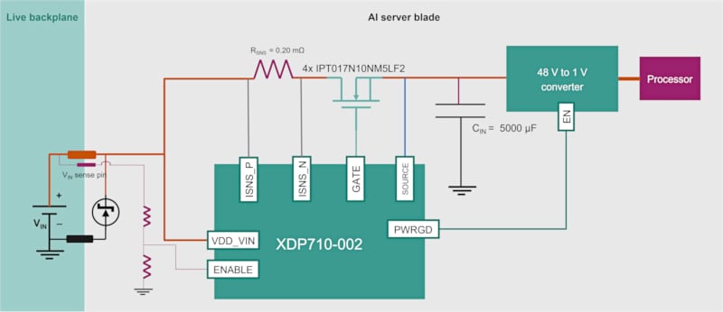
Figure 2. 4 kW hot-swap controller design. Image used courtesy of Bodo’s Power Systems [PDF]
Burst Mode vs. Continuous Mode
While operating on the DC SOA line, continuous power dissipation across the FET (VDS × ID) reduces reliability, especially with a larger capacitance extending the MOSFET’s time in the linear region. So, the 1 ms SOA line is used, turning the FET on for 1 ms to charge the capacitor, then off to cool down, and repeating.
During turn-on, the FET charges the input capacitor without feeding the load current, thereby storing energy. During turn-off, the controller slowly charges the capacitor, allowing the MOSFET to cool. In burst mode, the FETs operate at the 1 ms SOA line during high VDS and switch to continuous mode at lower VDS, providing ~9 ms (adjustable) cooling time, thus enhancing reliability.
The mechanical connection of hot-plugging a server blade into the backplane often causes bouncing. The gate pulse to the inrush FET is provided only after the blade is securely plugged in to prevent bouncing. Therefore, a voltage-sense pin can be used, which is the last to connect with the backplane and is linked to the “Enable” pin of the hot-swap controller. The controller turns on the inrush FETs only when the voltage on the “Enable” pin is above a threshold for a set duration; otherwise, the CIN remains disconnected from the backplane.
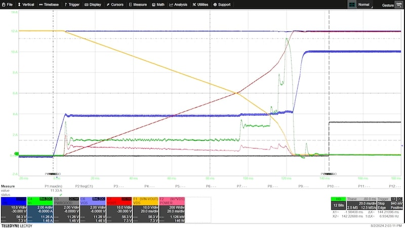
Figure 3. Typical turn-on waveforms of XDP XDP710-002 charging a 5000 µF capacitance. Image used courtesy of Bodo’s Power Systems [PDF]
Blade and Backplane Fault Protection
The backplane must be protected against faulty blades to shield other parallel servers. Detecting faults and isolating affected server blades quickly and safely by opening the inrush FETs is of utmost importance. External events like voltage variations/ surges also require protection to maintain system reliability and avoid server downtimes.
Hot-swap controllers offer protection against short circuits, overcurrent, overvoltage, undervoltage, overtemperature, and FET faults. They isolate faulty modules without damaging the backplane and alert the system via fault pins. FETs can be latched off, they can turn back on after self-clearing faults, or the controller can auto-retry based on settings.
Short-circuit detection is critical due to its potentially catastrophic impact. Modern controllers isolate faults in <1 µs using fast comparators and strong gate pull-downs but cause high voltage spikes. TVS diodes are used to clamp these spikes, ensuring the 100 V-rated FETs handle the surge safely. Additionally, warning alerts help prevent faults with preemptive adjustments, ensuring uninterrupted supply.
The hot-swap controller’s active monitoring module, accessible via PMBus, provides real-time accurate telemetry of voltage, current, power, temperature, and energy, with fault and warning statuses reporting. The capability to capture peaks and valleys helps identify potential fault events.
To enhance reliability and fault analysis, a black-box feature records telemetry data before, during, and after faults, allowing detailed analysis and troubleshooting.
Future Trends
Rising demands seek integrated solutions like eFuses, combining linear MOSFETs, hot-swap controllers, and current and temperature sensors into one package, thereby significantly reducing the size of hot-swap solutions.
eFuses offer enhanced reliability. Integrated temperature sensors provide real-time die temperature readings, shutting down the MOSFET at unsafe temperatures. Moreover, when paralleled, multiple eFuses ensure current sharing at startup.
AI server power consumption is expected to increase to 8/12 kW, necessitating backplane voltages up to 400 V. This requires new, more robust, and reliable hot-swap controllers and MOSFETs, as failures at such high voltages could be catastrophic.
This article originally appeared in Bodo’s Power Systems [PDF] magazine.