Facebook
 Google
 GitHub
 Linkedin
How SiC MOSFETs Address AI Data Center Efficiency
Increasing hyperscale data center power demands are setting tough new requirements for efficient power conversion, which are critically needed so the existing electricity grid can keep up with the AI-driven boom in cloud computing.
Everything is stored in the cloud today, but where exactly is the cloud?
The answer is in a data center—and the never-ending demand for more pictures, videos, and everything else means the data center industry is booming.
According to the International Energy Agency (IEA), the explosive growth in the artificial intelligence (AI) sector is massively increasing the power demands on data centers, with their electricity consumption expected to more than double in the three years from 2022 to 2025. In addition to the increased costs, this is also putting a strain on aging electricity infrastructures, which are already running out of power and requiring new investment.
Surging data center electricity usage translates into a growing demand for power semiconductors that can efficiently convert electric power to reduce costs and lower greenhouse gas emissions as we head toward net zero. There is also a continued push for power systems with lower total system cost and more compact size.
Cooling is a huge issue for data centers and is estimated to account for more than 40% of electricity usage in most data centers today. In fact, when we talk about the efficiency of power supplies, the energy wasted is simply dissipated as heat, which the data center’s air conditioning systems need to remove. Thus, more efficient power conversion equals less heat, which equals less money spent on electricity for cooling.

AC-DC Conversion Requirements in Data Centers
Power density within data centers is growing fast, with power supply unit (PSU) vendors working to pack the highest power capabilities into a standard 1U rack (Figure 1). Just a decade ago, the average density per rack was something like 4 to 5 kW. Still, today’s hyperscale cloud companies—such as Amazon, Microsoft, or Facebook—typically look at more like 20 or 30 kW for each rack. Some specialist systems go further, mandating 100 kW per rack or beyond.
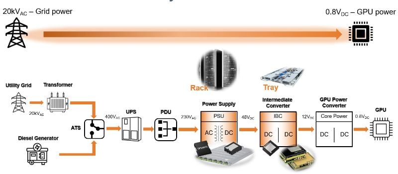
Figure 1. Data Center power delivery from grid to GPU
These high power densities require compact power supplies that fit into a small form factor. They also need high efficiency, as there is less space to dissipate and manage the heat produced by power conversion losses.
However, the challenge is not just about improving overall efficiency–power supplies must also meet the specific needs of the data center industry. For example, all AI data center PSUs should meet the stringent Open Rack V3 (ORV3) base specification.
Recently, server rack providers launched a new AC-DC PSU that operates from a nominal input range of 200 to 277 VAC with an output of 50 VDC. It meets the ORV3 standard, which requires peak efficiency of over 97.5% from 30% to 100% load condition and minimum efficiency of 94% from 10% to 30% load condition.
Server Rack Power Supply Unit Topology Choices
As a key part of AC-DC conversion in PSUs, achieving high efficiency in the power factor correction (PFC) stage is essential. The PFC stage shapes the input current to maximize the ratio of useful power to total input power. PFC design is also key in meeting electromagnetic compatibility (EMC) regulations such as IEC 61000-3-2 and ensuring compliance with energy efficiency specifications such as Energy Star.
The best approach to the PFC stage in many applications, particularly in data centers, is the “totem pole” PFC topology. This is typically used for the PFC block in the power supply for 3 kW to 8 kW systems in data centers (Figure 2). Based on MOSFETs, totem pole PFC stages improve AC power supplies' efficiency and density by removing the bulky and lossy bridge rectifier.
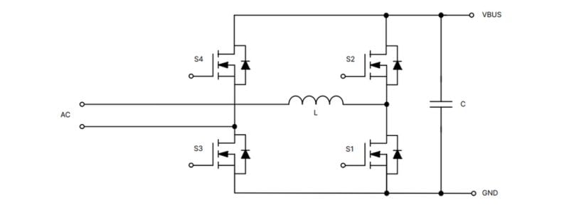
Figure 2. Totem Pole PFC Stage
However, to achieve the 97.5% or better efficiency mandated by the hyperscale data center companies, a totem pole PFC requires MOSFETs using a “wide bandgap” semiconductor like silicon carbide (SiC). Today, all the PFC stages use SiC MOSFETs for the fast-switching leg, while silicon-based super junction MOSFETs are used for the phase or slow leg.
SiC MOSFETs have better performance and increased efficiency compared to silicon MOSFETs. They also provide superior performance at high temperatures, robustness, and can operate at higher switching frequencies.
Compared to silicon-based super junction MOSFETs, SiC MOSFETs have a lower figure for energy stored in its output capacitance (EOSS), which is critical at low load conditions, as the major switching loss in PFC stages is caused by devices with a relatively high EOSS and gate charge. Lower EOSS minimizes energy losses in switching, thus enabling higher efficiency in the totem pole PFC fast leg. In addition, a SiC MOSFET displays better (positive) temperature co-efficient of RDS(ON) compared to a silicon-based super junction MOSFET because of superior thermal conductivity, which is three times better than silicon-based devices.
The following plot illustrates the relationship between on-resistance and junction temperature for a 650 V SiC MOSFET. (Figure 3) (On-resistance at junction temperature 175 degrees Celsius is 1.5 times higher than room temperature.)
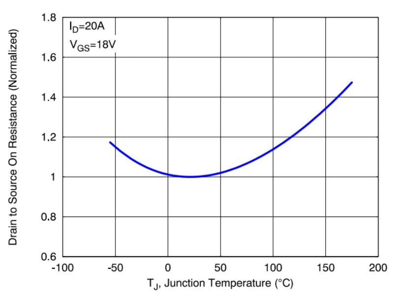
Figure 3. 650 V SiC MOSFET - On-Resistance vs. Junction Temperature
Similarly, the following plot (Figure 4) illustrates the relationship between on-resistance and junction temperature for a 650 V super junction MOSFET. On-resistance at junction temperature 175 degrees Celsius is over 2.5 times higher than room temperature.
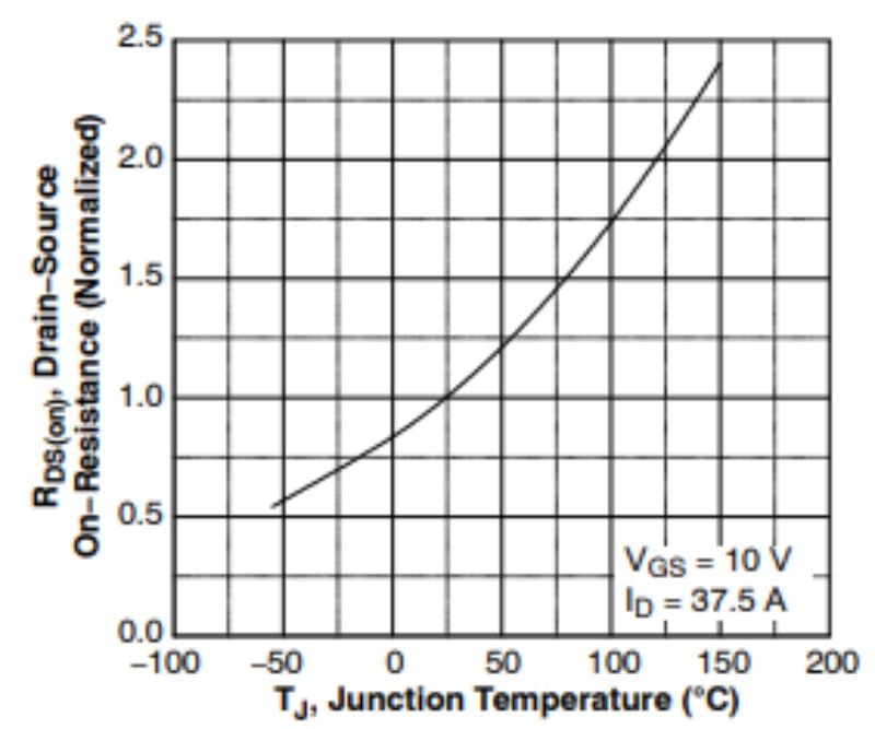
Figure 4. 650 V Si Super Junction MOSFET: On-Resistance vs. Junction Temperature
Comparing a similarly rated RDS(ON) device between a silicon-based 650 V super junction MOSFET and a 650 V SiC MOSFET, the RDS(ON) of a 650 V super junction MOSFET increases to about 50 mohm at junction temperature (Tj) of 175-degree Celsius. At the same time, a 650 V SiC MOSFET’s on-state resistance (RDS(ON)) is around 30 mohm at Tj of 175 degrees Celsius. During high-temperature operation, a 650 V SiC MOSFET has lower conduction loss.
In a totem pole PFC slow leg block and LLC block, conduction losses dominate the overall power loss. SiC MOSFET’s lower RDS(ON) at higher junction temperature improves system efficiency.
SiC MOSFETs excel in totem pole PFC topologies due to their minimal RDS(ON) increase at high temperatures and outstanding EOSS, contributing to enhanced efficiency and reduced energy losses.
Efficient SiC MOSFET Technology
Onsemi’s 650 V M3S EliteSiC MOSFETs, including the NTBL032N065M3S and NTBL023N065M3S, provide best-in-class switching performance and greatly improve system efficiency in PFC and LLC stages. M3S EliteSiC technology surpasses its predecessor with a 50% reduction in gate charge, 44% lower EOSS and 44% less stored charge in its output capacitance (QOSS). This superior EOSS figure improves the system efficiency at light loads when used in a hard switching topology in the PFC stage. Additionally, a lower QOSS simplifies resonant tank inductance design for soft-switching topologies in the LLC stage.
The M3S EliteSiC MOSFETs dissipate less heat thanks to excellent switching performance and power efficiency. In addition to helping reduce cooling requirements in data centers, the M3S EliteSiC MOSFETs can “work cool” in PFC and DC-DC blocks with a high operating frequency, such as in a wallbox DC charger for electric vehicles.
The M3S EliteSiC MOSFETs provide the gate charge Qg and reduce gate drive losses. Excellent Qgs and Qgd also help reduce switching turn-on and turn-off losses. In the LLC block, the VDS transition from off-state to diode conduction requires charging the output capacitance. To achieve this quickly, a low transient output capacitance (COSS(TR)) is necessary. Transient COSS is very important here as this minimizes the circulating losses from the resonant tank and allows for shorter dead time for the LLC, resulting in reduced circulating losses on the primary side. An on-state low resistance minimizes conduction losses, and the low EOFF helps keep switching losses at a minimum. Overall, the higher system efficiency is the single most important performance criterion, making SiC MOSFETs an optimal choice in data center PFC and LLC stages.
EliteSiC MOSFETs are suitable for energy infrastructure applications, such as photovoltaic generators, energy storage systems, uninterruptible power supplies, and EV charging stations. Design engineers can reduce their overall system size with the M3S EliteSiC MOSFETs, which aid in increasing the operating frequency. From the system point of view, design engineers can reduce system costs with M3S EliteSiC MOSFETs compared to silicon-based 650 V super junction MOSFETs.
Overall, new EliteSiC MOSFETs are competitive against super junction MOSFETs available in the market regarding cost, EMI, high-temperature operation, and switching performance based on the same RDS(ON). The 650 V M3S EliteSiC MOSFET approaches lower RDS(ON) than super junction MOSFETs in the same package, which improves system efficiency in LLC topology. It scores highly over other silicon alternatives because of its much lower switching losses.

Figure 5. Advantages of 650 V M3S EliteSiC MOSFETs
Takeaways
The PFC and LLC stage efficiency can be significantly improved with SiC MOSFETs. Onsemi’s 650 V M3S EliteSiC MOSFETs significantly improve PFC and LLC stage efficiency in hyperscale data centers. The 650 V M3S EliteSiC MOSFETs offer lower gate charge, EOSS, and QOSS, boosting efficiency and simplifying design for hard-switched topologies used in PFC and LLC stages, thus helping reduce electricity usage and cutting operating costs.