Facebook
 Google
 GitHub
 Linkedin
6500 V X-Series High Voltage IGBT Modules
This article introduces Mitsubishi Electric's 6500V X-Series High Voltage IGBT module for power modules operating at 150ºC junction temperature.
The 6500 V X-Series high current IGBT power module breaches the technological barrier for operating at 150 °C junction temperature by employing the 7th Generation IGBT and Diode chip-sets. This could potentially unlock the possibility of discovering new horizons in inverter design.
Introduction
On 29th Sep. 2015 MITSUBISHI ELECTRIC CORPORATION launched the first product of the new high voltage IGBT X-Series product family [1] - the IGBT module with a blocking voltage of 6500 V and a rated current of 1000 A. CM1000HG-130XA is the highest-rated device in the industry for this voltage class (operating temperature of 150 °C). A key design aspect of the X-Series is the combination of the already well know and proven R-Series package technology with the newly developed 7th generation IGBT and Diode chip-set. The CM1000HG-130XA package outline is shown in Figure 1. It is the standard package type with a high isolation voltage of VISO=10,2 kV and a footprint size of 190 mm x 140 mm and this same package is used in the previous generation R-Series. For many years R-Series has been demonstrating excellent reliability for different applications (such as traction, industrial drives and power transmission) requiring a high demand on quality as well as reliability.
Durability at a high operating temperature of 150 °C was already demonstrated and proved with the R-Series package technology for power modules in the voltage classes: 3300 V and 4500 V. The new developed 7th generation chip-set allow for an increase in the operating temperature of up to 150 °C for the IGBT modules in the 6500 V class.
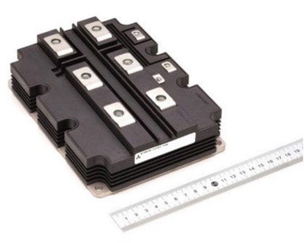
Figure 1: CM1000HG130XA X-Series IGBT module package outline.
7th generation IGBT and Diode chip-sets contributes to the enhancement of power module current density.
The 7th generation chip was developed and optimized especially for low power loss and high temperature operation. For both IGBT and Diode chips the new guard ring structure (edge termination) was developed allowing an increase in the active chip area [2]. It was possible to increase the IGBT active chip area by about 28%. A comparison of the 6500 V X-Series IGBT chip with an IGBT chip of a previous generation is shown in Figure 2. As a result of the reduced current density, a lower forward voltage drop could be achieved. This contributes to lower steady-state power losses. On the other hand thermal resistance between the junction and the case could be decreased to Rth(j-c)Q=11 K/kW for the IGBT and to Rth(j-c)D=17 K/kW for the diode respectively.
Additionally, the CSTBT (III)TM trench gate structure contributes to the reduction of the IGBT forward voltage drop. The Diode has an RFC structure that results in a soft reverse recovery switching even at higher values of stray inductance [4]. Both chips - IGBT and Diode possess a positive temperature coefficient that makes paralleling of the X-Series quite easy. At the junction temperature of 150°C the device has a typical leakage current of I CES=30 mA and it is comparable to leakage current values of previous generation modules at 125 °C junction temperature. A low leakage current value at a high junction temperature in combination with a robust chip design enables safe switching at high temperatures and thereby permits increasing the operation temperature of the 6500V X-Series up to 150°C.
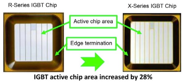
Figure 2: IGBT Chip comparison between 6500 V R- and X-Series.
Electrical characteristics
A brief overview of the key electrical parameters for the CM1000HG-130XA module at the rated current of 1000 A and junction temperature of 150 °C is shown in Table 1.
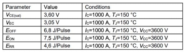
Table 1: Overview of electrical parameters
The new 7th gen chip-set has the same chip arrangement as the highly optimized tried and tested R Series chip-set. Furthermore, the internal layout of the main and the auxiliary terminals were maintained unchanged. As a result, the switching performance of the new X-Series can rely on the long and proven record of the R-Series. The below figures show the typical switching wave forms of the CM1000HG-130XA device. Figure 3 shows the IGBT turn on wave forms at nominal conditions. Figure 4 shows the typical IGBT turn off wave forms at nominal conditions. The module voltage and current have soft characteristics without any oscillations. The collector emitter peak voltage at turning off the collector current I C=1000 A at a DC-link voltage of VCC=3600 V. with a stray inductance of LS=150 nH is about 4200 V only.
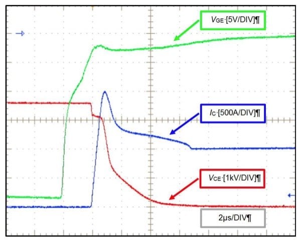
Figure 3: CM1000HG-130XA IGBT turn on wave forms at TJ=150 °C, VCC=3600 V, IC=1000 A, RG(on)=1,8 Ohm.
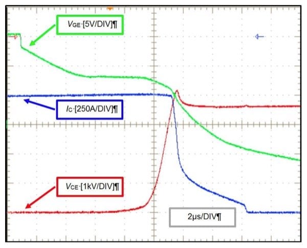
Figure 4: CM1000HG-130XA IGBT turn off wave forms at TJ=150 °C, VCC=3600 V, IC=1000 A, RG(off)=30 Ohm.
The typical CM1000HG-130XA reverse recovery waveforms are shown in Figure 5. Here too, the diode voltage and current have soft switching characteristics.
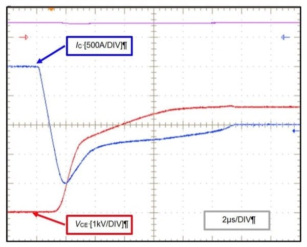
Figure 5: CM1000HG-130XA FWDi reverse recovery waveforms at TJ=150 °C, VCC=3600 V, IC=1000 A, RG(on)=1,8 Ohm.
Application benefits of using the newly developed CM1000HG130XA device.
The achievable inverter output current is the most important performance parameter for an IGBT module used for an inverter application. Figure 6 is the simulation result showing the inverter output current versus switching frequency for a three-phase inverter using a sine-triangle PWM control algorithm. The new developed CM1000HG-130XA device is compared with the previous generation module CM750HG-130R. Simulation was performed at the same junction-case temperature swing of ∆T(j-c)=20 K and maximum junction temperature of TJ=125 °C. The curves are normalized with respect to the previous generation CM750HG-130R device and a switching frequency of fsw=300 Hz. The new device CM1000HG-130XA has more than 20% better performance at fsw=300 Hz. At a switching frequency of fsw=150 Hz, the performance of the CM1000HG-130XA device is 30% greater compared to the previous generation. This advantage at low switching frequencies is especially beneficial for multi-level grid applications like HVDC (High Voltage Direct Current) power transmission and SVC (Static Var Compensation).
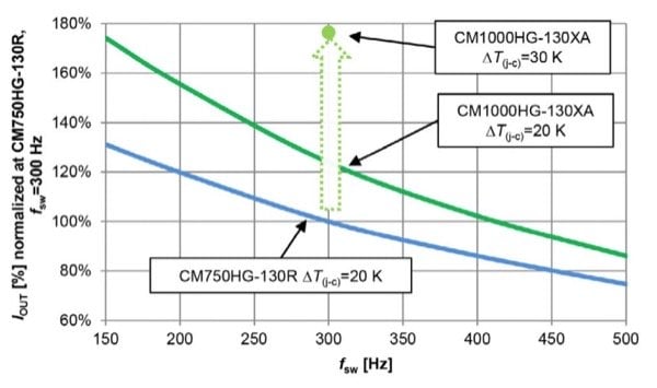
Figure 6: Inverter output current versus switching frequency at VCC=3600 V, cos(φ)=0,9, m=1, TJ=125 °C.
In case the junction-case temperature is increased from 20 K to 30 K for CM1000HG-130XA module, the output power can be increased by 80% as shown in Figure 6. As a result, applications with high short-time overload conditions would not need derating for nominal operation (attributable to the maximum junction temperature limitation of 125 °C).
The capacity of the new module to operate at an increased junction temperature of 150 °C would greatly benefit applications such as traction and industrial applications with air-cooled heat sink (compared to the modules operating at 125°C). This can be demonstrated by a simple calculation - for example – a heat sink (in a typical air-cooled application) with an Rth(f-a)=70 K/kW would result in a 70 K temperature difference between the fin and the ambient for a power dissipation of 1000 W. Additionally, it must be noted that for air-cooled applications the temperature increase internally within the module is not significant. Thus, (considering a linear dependency between power loss increase and output power increase), we can realize an output power increase of 20%. By increasing the power dissipation by 20% (1200 W), the heat sink temperature will increase additional by 14 K (to 84 K) and that can be easily buffered by the CM1000HG130XA device.
Increasing the operating temperature of the 6500 V power module allows further optimization in the cooling system such as:
- Reduction in the water flow rate in liquid-cooled applications
- Using less expensive liquid heat sinks
- Reducing the cost for heat exchanger in liquid cooled systems
- Using forced air cooling instead of water cooling
- In some cases, the paralleling of traditional type modules can be avoided by using of ingeniouse CM1000HG-130XA device.
The X-Series uses a well-known standard package and this allows for quick optimizations and improvements requiring no significant redesign/development to existing inverter designs. The cooling system can be optimized and higher inverter power density can be realized by using CM1000HG-130XA device with increased operating junction temperature.
The advantage of increased operating temperature can be easily translated into either a simplification of the existing cooling system (maintaining a modest output power) or increase of the output power (maintaining an existing cooling system).
About the Author
Eugen Wiesner is an Application Engineer at Mitsubishi Electric Europe B.V., Ratingen Germany, one of the branches of the Japanese multinational electronics and electrical equipment company, Mitsubishi Electric Corporation. the company manufactures electrical and architectural equipment and is one of the major producers of photovoltaic panels.
Eugen Stumpf is the Application Engineering Manager at Mitsubishi Electric Europe B.V., one of the branches of the Japanese multinational electronics and electrical equipment company, Mitsubishi Electric Corporation. the company manufactures electrical and architectural equipment and is one of the major producers of photovoltaic panels.
Yumie Kitajima works at Mitsubishi Electric Corporation which is one of the world's leading names in the manufacture and sales of electrical and electronic products and systems used in a broad range of fields and applications.
References
- http://www.mitsubishielectric.com/news/2015/0929.html
- Ze Chen, et al, “A balanced High Voltage IGBT Design with Ultra Dynamic Ruggedness and Area-efficient Edge Termination,” Proc. ISPSD 2013, p 37, Kanazawa, Japan.
- Kenji Hatori, “The Next Generation 6.5 kV IGBT Module with High Robustness”, PCIM Europe 2014.
- Fumihito Masuoka, “Great Impact of RFC Technology on Fast Recovery Diode towards 600 V for Low Loss and High Dynamic Ruggedness”, ISPSD 2012.”
This article originally appeared in the Bodo’s Power Systems magazine.