Facebook
 Google
 GitHub
 Linkedin
Intro to High-voltage Battery Disconnect Switches
This article introduces high-voltage battery disconnect switches, where transistors have replaced the old-fashioned relays.
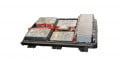
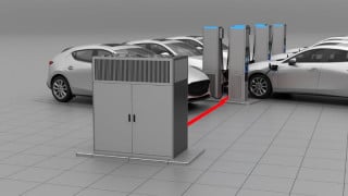
Electric cars currently on the market use 400 and 800 V batteries with nominal currents above 200 amperes, which could be lethal if this high voltage and current were connected to the chassis or any conductive part of the car. To prevent such a scenario, manufacturers use high voltage and high current direct-current contactor relays, disconnecting the battery plus and minus rail from the high-voltage-board net shown in Figure 1.

Figure 1. Battery disconnect switch. Image used courtesy of Bodo’s Power Systems [PDF]
Relay Challenges
The pre-charge circuit is needed if relays are used for charging the direct current (DC) link capacitor parallel to the inverter, which has an inrush current depending on its size, voltage, and time transients. This circuit closes first and opens after the DC link voltage is nearly reached. If semiconductors are used instead, this pre-charge is not needed anymore.
Relays are electromechanical devices with certain challenges in their application. One major challenge is the arcing between two switch contacts, an electric discharge caused by the voltage across them and sustained by the current running through them. Arcing leads to a shortened lifetime or, worst case, destruction if the contacts are welded together. Relay providers have several solutions to overcome this problem, such as a capacitor across the load, gas-filled chambers, etc. The temperature range from HV DC relays is often limited to -40°C to 85°C and the switching speed is in the range of several tens of milliseconds.
Alternative to relays is bi-directional solid-state semiconductor switches, described below. It focuses on the main contractor, aware that auxiliary circuits also need these switches.
Implementing semiconductors as relay replacement is done so that two transistors are placed in anti-series to block the current in both directions (see Figure 2 below), with an n-channel MOSFET. Alternatively, every other type of FET could be generally used. VisIC core competence is in wide bandgap Gallium Nitride (GaN) FETs in a Direct Drive Configuration, hence the reason for proposing them for the HV-BDS.
What are the requirements for the FETs used in the BDS? During normal operation, the switch is constantly on, therefore RDSon is a dominant parameter, defining the conduction losses (Pcon=I²*RDSon). A desired minimum can be achieved by the technology itself and by the parallelization of multiple dies. Parallelization is critical for proper current sharing, which must be guaranteed. It depends strongly, among other parameters, on a flawlessly printed circuit layout with symmetrical stray inductances. Depletion mode GaN FETs provide high electron mobility of approx. 1500 cm²/V*s from the 2-dimensional electron gas (2DEG) combined with superior reliability.
Why are GaN devices a suitable candidate for an HV-BDS? Baliga (2016) said: “...the predicted specific on-resistance of 0.4mohm/ cm² is 180 times smaller than the ideal specific on-resistance for a conventional silicon device”. Commercial devices are currently not at this prediction, but even if the resistance is double, it would be 90 times smaller than a silicon switch. Due to that, GaN transistors can be made either much smaller for the same RDSon or have much less resistance for the same size and are a perfect fit for battery disconnect switches. VisIC’s direct drive configuration, set out in Figure 3, shows how to control the GaN device, producing multiple benefits compared to other solutions on the market, e.g., no reverse recovery losses, increased reliability, etc.

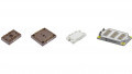
Figure 2. Block schematic. Image used courtesy of Bodo’s Power Systems [PDF]

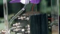
Figure 3. Direct Drive GaN. Image used courtesy of Bodo’s Power Systems [PDF]
Challenges Facing Gallium Nitride
What are the challenges facing Gallium Nitride in this application? Lateral GaN FETs do not have any avalanche breakdown tolerance (Baliga). VisIC switches have, therefore a high enough breakdown voltage margin. The 650 V-rated devices have a static blocking voltage above 1600 V, providing robustness to surge and overvoltage tested by Q. Song et al. (2022) at Virginia Tech. The dynamic breakdown voltage is even more than 2 kV. In a short circuit event, the device must withstand the high currents running through the channel. Song showed that the 22 mOhm device from VisIC can handle repetitive 358A for 5 microseconds. Besides this technological solution, a discrete approach can be implemented to protect the FET in a short circuit event within 100 ns. A detailed explanation can be found in the Short Circuit Protection Application Note APN-01650- 0003 Rev1.0.
References:
1. Baliga (2016): Gallium Nitride and Silicon Carbide Power Devices, World Scientific
2. VisIC Technologies Short Circuit Protection Application Note APN-01650-0003 Rev1.0
3. Q. Song et al., “Evaluation of 650V, 100A Direct-Drive GaN Power Switch for Electric Vehicle Powertrain Applications,” 2021 IEEE 8th Workshop on Wide Bandgap Power Devices and Applications (WiPDA), 2021, pp. 28-33, doi: 10.1109/ WiPDA49284.2021.9645143.
This article originally appeared in Bodo’s Power Systems [PDF] magazine.