Facebook
 Google
 GitHub
 Linkedin
3.3 kV Full SiC MOSFETs – Towards High-Performance Traction Inverters
This article highlights the benefits of using the new Full SiC MOSFETS in traction applications and flexible converter designs.
Mitsubishi Electric is developing a new Full SiC device rated for 3.3 kV and 750 A. The device comes in the most recent LV100 package, which is especially suitable for traction application and modular converter designs. This article introduces the new Full SiC device and demonstrates the benefits of traction applications.
Introduction
Power semiconductor devices made of silicon carbide (SiC) are regarded as the major innovation in modern power electronics. Compared to classical silicon (Si) devices, SiC enables more efficient and more compact converters to save electric energy and valuable materials.
Over the last 20 years, Mitsubishi Electric has developed and commercialized SiC devices for several voltage classes and various applications [1]. Now, after years of in-field experience with different SiC modules in traction applications [2], Mitsubishi Electric makes the next big step. With a rated voltage of 3.3 kV and a current of 750 A, the new Full SiC dual-module is especially intended for high-performance traction converters and flexible converter designs. The type name of this new device is FMF750DC-66A.
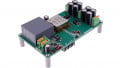
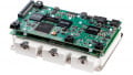
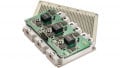
Due to the fast switching transients, Full SiC devices require an appropriate package offering low stray inductance. Therefore, the FMF750DC-66A, as shown in Figure 1, comes in the most advanced package for this voltage and power class: the LV100 package. This package offers a stray inductance below 10nH and simpler parallel connection of several modules. Moreover, the internal package design ensures optimal current sharing among the semiconductor chips inside a module.

Figure 1. The new 3.3 kV Full SiC device is rated for 750 A and comes in the most recent LV100 package
Comparison with Silicon Devices
The following chapter compares the FMF750DC-66A with two different Si devices that also come in the same LV100 package. These two devices of the same voltage class are rated for 450 A and 600 A. In the following, they are referred to as CM450DA-66X and CM600DA66X according to their respective type name. Figure 2 shows the static characteristics of all modules and, hence, demonstrates nicely the general difference between bipolar IGBTs and unipolar MOSFETs. It should be noted that all device characteristics are given for the respective maximal junction temperature being 150°C for the Si devices and 175°C for the FMF750DC-66A. Due to the linear current-voltage dependency of MOSFETs, the voltage drop at low currents is substantially lower than for bipolar IGBTs (cf. Figure 2 (a)). As shown in Figure 2 (b), also the voltage drop of the FMF750DC-66A in reverse direction is much smaller compared to the freewheeling diodes of the Si modules, if both, the diode (SBD) and MOSFET, are conducting the reverse current (synchronous rectifier mode). Consequently, especially at low-load conditions, the use of unipolar devices increases converter efficiency significantly. The subsequent chapter quantifies this for a traction application.


Figure 2: Static characteristic of the Full SiC devices compared to the 450 A and 600 A silicon-based modules
Another very prominent advantage of Full SiC devices is the reduction of switching losses. Again, this effect results from the unipolar nature of the devices. The lack of reverse recovery and tail currents decreases switching energy and allows higher switching frequencies compared to Si devices. Figure 3 shows the sum of energy loss during turn-on, turn-off and reverse recovery. Compared to the Si-based IGBTs, the switching losses in the Full SiC module are reduced by 80–90%.
The following chapter quantifies and discusses the advantages of the converter design and intended applications.

Figure 3. Switching losses of the Full SiC module compared to Si-based modules
System-level Advantages
The first example regards traction inverters with 750Hz switching frequency at 1500V dc-link voltage. The losses generated by the Si-based CM600DA-66X and the SiC-based FMF750DC-66A are compared. Figure 4(a) shows the energy savings using the FMF750DC66A instead of a CM600DA-66X. Especially at the vehicle’s part-load condition, the saving potential is enormous. Below 400A output current, the Full SiC devices save more than 50% to 80% of the energy loss by semiconductors (at the same device footprint).
Especially at part load, operational energy costs can be reduced. Moreover, due to higher efficiency and the higher operational junction temperature of the FMF750DC-66A, the maximal power in rectifier operation increases. As illustrated in Figure 4(b), maximal output power increases by roughly 60% at an exemplary switching frequency of 750Hz. Since the rectifier mode serves the recovery of energy when the vehicle slows down, potentially more energy can be recycled and fed back into the electricity network. Moreover, this reduces stress on the conventional braking system.
The second example considers a grid-connected converter operating at a power factor of 0.9. The maximal switching frequency in dependence on the output current is calculated. Figure 5 shows the results considering a cooling water temperature of 40°C. Consequently, the maximal switching frequency for the FMF750DC-66A increases by a factor of 5 to 9 compared to the CM600DA-66X at the same current level.
The higher switching frequency allows converter manufacturers a grid-filter design for higher resonance frequencies. Consequently, the required inductance and capacitance values for an LCL filter decrease. This, in turn, decreases the filter’s size, cost, and losses. Moreover, the converter achieves a more dynamic control. Furthermore, for machine side inverters or dc-dc converters, the higher switching frequency enables the design of more compact high-speed drives and medium-frequency converters [3,4].


Figure 4. Comparison of FMF750DC-66A with CM600DA-66X
Besides the switching frequency increase, Figure 4(b) has already demonstrated that keeping the switching frequency constant, the converter achieves significantly higher output power. The fact that the FMF750DC66A comes in the same package as the CM450DA-66X and CM600DA-66X allow more flexible converter designs and fast development (having a similar inverter configuration as Si-based inverter).


Figure 5. Maximal output current in dependence on switching frequency
Beyond the discussed benefits in traction and grid applications, the FMF750DC-66A makes further benefits accessible. Figure 6 tries to illustrate the advantages of the FMF750DC-66A at different system levels: at the module level, at the converter level, and at the application level. In general, the use of new FMF750DC-66A makes sense in those applications where these system-level advantages potentially over-compensate the higher costs of today’s SiC-modules compared to established silicon devices.

Figure 6. Opportunities enabled by the Full SiC FMF750DC-66A
Mitsubishi Electric offers an extensive line up in the state-of-the-art LV100 package. Now, a 750 A Full SiC module is added to the 3.3 kV line up.
The FMF750DC-66A Full SiC module increases the converter’s power density by increased switching frequency and higher maximal junction temperature of 175°C. Moreover, the module achieves higher system efficiency. Especially at part load conditions or rectifier operation, the FMF750DC66A reduces the inverter losses by 50 to 80%.
The FMF750DC-66A comes in the same low-inductive LV100 package as its Si counterparts. For converter manufacturers, this simplifies the transition from Si to SiC and gives tremendous flexibility.
About the Authors
Dr. Nils Soltau received a Diploma Degree in Electrical Engineering and Information Technology from RWTH Aachen University, Aachen, Germany, in 2010. Since March 2010, he has been with the Institute for Power Generation and Storage Systems (PGS), E.ON Energy Research Center, RWTH Aachen University, where he builds up a 5 MW DC-DC converter. His research interests include high-power DC-DC converters, medium-voltage power semiconductors, and magnetic components.
Eugen Wiesner is an Application Engineer at Mitsubishi Electric Europe B.V., Ratingen Germany, one of the branches of the Japanese multinational electronics and electrical equipment company, Mitsubishi Electric Corporation. the company manufactures electrical and architectural equipment and is one of the major producers of photovoltaic panels.
Kenji Hatori works as an Assistant Manager on Project Management at the Mitsubishi Electric Corporation, Fukuoka Japan, a branch of the Japanese multinational electronics and electrical equipment company, Mitsubishi Electric Corporation, that specializes in power device works.
Hitoshi Uemura works at the Mitsubishi Electric Corporation, Fukuoka Japan, a branch of Mitsubishi Electric Corporation which is one of the world's leading names in the manufacture and sales of electrical and electronic products and systems used in a broad range of fields and applications.
References
- E. Thal and J. Yamada, “SiC Power Modules for a Wide Application Range,” Bodo’s Power Systems, Sep 2017.
- Mitsubishi Electric, Mitsubishi Electric Installs Railcar Traction System with AllSiC Power Modules on Shinkansen Bullet Trains, Press Release No. 2942, June 2015.
- L. Luise and others, Design Optimization and Testing of High-Performance Motors: Evaluating a Compromise Between Quality Design Development and Production Costs of a Halbach-Array PM Slotless Motor, IEEE Industry Applications Magazine, 2016.
- M. Claessen, D. Dujic, F. Canales, J. K. Steinke, P. Stefanutti and C. Vetterli, Traction transformation - A power-electronic traction transformer, ABB Review, 01/2012.
This article originally appeared in the Bodo’s Power Systems magazine.