Facebook
 Google
 GitHub
 Linkedin
Modular, High-Power SiC Traction Inverters Accelerate Mobility Electrification Beyond Cars
Freight transportation, off-road and industrial vehicles, marine applications, and aviation contribute more than 55% of the total greenhouse gas emissions from internal combustion engines. Electrifying these powertrains could make a difference in fighting climate change, but the vast array of units is associated with a confusing diversity of types and platforms.
This article is published by EEPower as part of an exclusive digital content partnership with Bodo’s Power Systems.
Engineers need all the help they can get to develop new electric drives quickly. The differences are more than physical regarding size, shape, and weight constraints. The functional and electrical safety requirements and environmental conditions depend highly on applications and geographical markets. On the other hand, the competitive situation between all manufacturers demands a fast time to market.
For performance and reliability, silicon carbide (SiC) is the power semiconductor technology of choice. While range anxiety is one issue that has moved the passenger car market away from silicon and towards more energy-efficient SiC, vehicles such as buses operate on known routes and off-road vehicles cover relatively short distances. For these applications, SiC’s high-voltage capability permits faster charging for quicker turnaround times, and its ability to operate at high temperatures helps maximize reliability. Moreover, modules require fewer SiC devices to share the duty, and SiC MOSFETs can be smaller in relation to breakdown voltage than their silicon counterparts. Hence, savings in module size are also possible.
However, SiC power devices are not a direct drop-in replacement for silicon MOSFETs or IGBTs. Arranging proper control of the gate to ensure fast and smooth switching transitions at high frequencies is not straightforward. Further challenges include integrating hardware components, especially the inverter and the intelligent power module, and setting up and calibrating the motor control software.

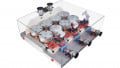
Figure 1. CISSOID’s high-voltage SiC inverter reference design. Image used courtesy of Bodo’s Power Systems [PDF]
Accelerated Development
To help overcome the development challenges and accelerate the time to market for robust and reliable SiC power modules (Figure 1), Cissoid has produced a SiC traction-inverter platform and reference design. Drive makers can use this to build systems capable of operating from battery voltages up to 850V. The hardware is modular and scalable to produce designs of various power ratings.
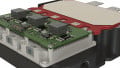
The reference design solves aspects of the inverter that are notoriously difficult and time-consuming. The core components include a 3-phase 1200 V intelligent power module (IPM), already integrated with a gate driver optimized for SiC applications and designed to withstand elevated temperatures (Figure 2). The driver provides peak gate currents over 10 A and can operate in ambient temperatures up to 125°C.

Figure 2. The Intelligent Power Module comprises a SiC power stage with pin-fin cooling and a top-mounted gate driver. Image used courtesy of Bodo’s Power Systems [PDF]
Because the SiC gate driver is already integrated with the power module, users can start their projects with a solution that is already validated and optimized for fast switching speed and low losses, immune to high dI/dt and dV/dt effects, and that contains robust protections for the power stages. As a result, the number of iterations required to fine-tune module performance and ensure proper thermal management is significantly reduced. Additional hardware in the reference design includes DC-current and phase-current sensors, EMI filtering, a compact liquid cooler, and a high-density DC-link capacitor. The DC-link capacitors are specifically developed for the inverter platform and cover various voltage and current options.
Software Control and Calibration
To complete the reference design, there is also an e-motor control board with an application-specific processor and software, pre-certified to the ISO 26262 standard, ASIL level D, for functional safety. The motor control software allows a wide range of adjustments without compromising the functional safety certification, giving the flexibility to optimize the motor behavior as required in the end-use case. The users can run their custom application software on top of this.
The control board is designed around the Silicon Mobility OLEA T222 field-programmable control unit (FPCU). This approach allows the reference design to combine the software-based flexibility of a conventional processor with hardware acceleration to ensure real-time performance up to the highest desired motor speed. By including the control board, the reference design also helps users avoid the usual mechanical and electrical integration challenges when bringing the control board and Intelligent Power Module together.
The OLEA App Inverter is a flexible and fully customizable control software (Figure 3) that matches any electric powertrain configuration and power range thanks to configuration and calibration parameters that can be modified offline or in real time. The software also has a debugging and calibration framework, including a graphic interface.

Figure 3. The OLEA App Inverter control software provides multiple features to regulate and optimize motor operation. Image used courtesy of Bodo’s Power Systems [PDF]
Using the OLEA Composer, developers can shorten the time required to optimize the motor control software.
SiC Inverter Performance
After the parameters are set up, the motor can be tested, and the efficiency of the inverter-motor combination can be mapped. Figures 4a and 4b compare the performance of the SiC-based inverter with a silicon-IGBT inverter tested under similar real-world conditions.

Figure 4a. SiC inverter performance up to 260 kW @ 13500 rpm, showing efficiency across speed and torque range. Image used courtesy of Bodo’s Power Systems [PDF]

Figure 4b. The silicon-based inverter up to 120 kW @ 11500 rpm has impaired torque capability (see cross-points) under comparable conditions. Image used courtesy of Bodo’s Power Systems [PDF]
Setting Up and Calibrating the Drive
The OLEA Composer tools suite helps users get the motor spinning according to the customer’s specifications. It assists in performing calibration of parameters such as voltage, power rating, speed, and torque to reach an optimal working range. Once this is complete, the inverter-motor efficiency can be mapped.
Setup and calibration are completed in four steps:
Step 1: Software parameters configuration
- Configuration of the OLEA App Inverter software according to the e-motor parameters.
Step 2: Inverter hardware setup
- Setup of e-motor, including components such as resolver and temperature sensors. Connection of EV electronic control unit (ECU) and bench (e.g., CAN, safety) interfaces, power, and cooling interfaces.
- Check inverter safety interfaces with the test bench.
Step 3: Motor-control system calibration
- Open loop mode: calibration of current and voltage sensor signal conditioning chains by the OLEA T222 FPCU.
- Partial open-loop mode: position sensor offset calibration using resolvers or inductive sensors.
- Current closed-loop mode: internal PI controller tuning of ID and IQ vectors for field-oriented control (FOC).
- Torque control mode: fine-tuning the torque control loop for precision and dynamic response.
- Speed closed-loop mode: speed regulator calibration.
Step 4: Advanced System Optimisation
- Scaling of switching frequency: adjustment of the switching frequency depending on speed and phase currents.
- Dead time compensation: adjustment of the dead time compensation algorithm to minimize the phase-current harmonics.
- Flux Weakening: ID/IQ setpoints optimization for an efficient operation in the maximum torque per voltage (MTPV) region.
- SVPWM/DPWM: definition of the threshold between space vector pulse-width modulation (SVPWM) and discontinuous pulse-width modulation (DPWM), offering higher efficiency at high speed.
Using this approach allows tuning of the reference design to achieve efficiency greater than 99%, operating on a 700 V bus up to 4000 rpm, as shown below:

Image used courtesy of Bodo’s Power Systems [PDF]
These performance plots show how the greater efficiency of the SiC-based drive ensures a superior user experience. With increasing speed and load demand, the motor torque, when operating from the IGBT-based drive, becomes significantly reduced owing to its lower efficiency; the self-heating associated with the energy losses in the device cannot be dissipated without greatly increased cooling. In contrast, the highly efficient SiC-based drive can deliver closer to the maximum torque over a much wider speed and load range.
Pushing Electrification Beyond Cars
The bus, truck, and agricultural vehicles sectors present a good opportunity for electrification and reducing the environmental emissions burden. Silicon carbide power technology can help maximize both reliability and vehicle duty cycle and deliver superior efficiency compared to silicon IGBTs or MOSFETs. The complexities of designing with SiC and the imperative to ensure a fast time to market demand a flexible development platform to help designers satisfy the targets for various vehicle categories and types. A complete reference design that offers solutions to the main challenges when designing with SiC while also allowing flexibility and scalability to address different power ratings and battery voltages to handle small to large vehicles effectively minimizes design risks and helps accelerate time to market.
This article originally appeared in Bodo’s Power Systems [PDF] magazine.