Facebook
 Google
 GitHub
 Linkedin
Traction Inverter Functional Safety Design with SiC Auxiliary Power Supply
Proper design of a low-power auxiliary power supply within traction inverters is critical for ensuring the functional safety of EVs. Learn how SiC MOSFETs can play a critical role in this effort.
This article is published by EEPower as part of an exclusive digital content partnership with Bodo’s Power Systems.
In traction inverters, a low-power auxiliary power supply, typically a flyback converter, plays a crucial role in converting the 400 V or 800 V High-Voltage DC (HVDC) input to a Low-Voltage DC (LVDC) output. This auxiliary power supply serves as a backup during fault conditions, ensuring the electric drive system remains in a safe state by mitigating risks to vehicle occupants from hazardous conditions due to faults in the electric machine or traction inverter electronics.
Traction Inverter Functional Safety
Maintaining vehicle controllability is paramount from a safety perspective. Faults that impede a driver’s ability to control the vehicle are identified in the ISO 26262 Functional Safety (FuSa) Hazard Analysis and Risk Assessment (HARA). Several safety goals derived from the HARA are related to torque, such as preventing unexpected abrupt changes in torque or deviations from the commanded torque. Inverters are designed to seamlessly transition the electric drive system to a safe state upon detection of a non-recoverable fault.
One critical fault is the loss of the HVDC and 12 V power inputs. A blown fuse can result in the loss of 12 V to the main contactors that feed HVDC from the high-voltage battery to the traction inverter, as well as loss of 12 V to the inverter itself. Maintaining control of the electric machine during these conditions is crucial from a functional safety standpoint.
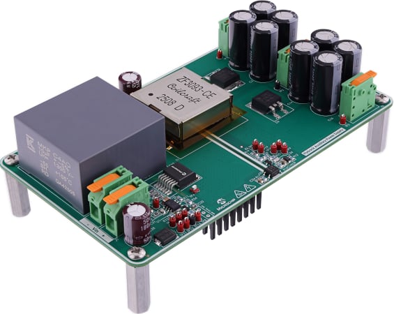
Figure 1. Microchip’s Auxiliary Power Supply for 800 V Traction Inverters. Image used courtesy of Bodo’s Power Systems [PDF]
A common solution is to include a backup power supply in the inverter design that converts HVDC to a low-voltage supply, powering the inverter’s control, sensing and gate drive circuits in the event of a loss of the 12 V input. This power supply is typically a flyback converter. In 800 V systems, silicon carbide (SiC) MOSFETs are used for their higher breakdown voltage rating compared to silicon MOSFETs. An 800 V system generally has a maximum continuous bus voltage in the 920-960 V range and a load dump voltage of 1000 V. Considering the reflected voltage and overshoot in a flyback converter, the voltage across the MOSFET’s drain-to-source can easily exceed 1200 V.
Figure 1 illustrates Microchip’s Auxiliary Power Supply for 800 V Traction Inverters, featuring an automotive-qualified mSiC MOSFET in a D2PAK-7L XL package with a 1400 V continuous and 1700 V repetitive voltage rating.
Looking deeper into the safety requirements, you will quickly determine that a typical 800 V flyback converter isn’t sufficient in this application. To maintain operation in the event of a loss of 12 V to both the inverter and to the main contactors, the backup power supply requirements become more stringent to ensure safe vehicle operation.
Consider an electric machine. It operates as a motor when it converts electricity to mechanical energy and as a generator when it converts mechanical energy to electricity. Specifically, when the torque and angular velocity are in the same rotational direction, the electric machine functions as a motor delivering power to the mechanical system for vehicle propulsion.
When the torque and angular velocity are in opposite directions, the electric machine functions as a generator. When the torque and angular velocity are of opposite rotational directions, the electric machine’s voltage and current are of opposite polarity. During regenerative braking, the electric machine operates as a generator, with the AC current flowing into the inverter for rectification into DC current to charge the high-voltage battery.
Electric Drive System Safe States
At the start of a fault condition where the inverter is no longer connected to the high-voltage battery, its internal DC-link capacitor and the capacitance of other high-voltage electronics systems on the bus are initially charged to the high-voltage battery voltage. The inverter quickly detects the loss of power and transitions the electric drive system into a safe state. This involves shorting the electric machine’s three-phase windings, commonly referred to as Active Short-Circuit (ASC) or “three-phase short,” or maintaining an opencircuit, also referred to as “six-switch open.” The safe state to transition to depends on a few factors, including the rotational speed of the electric machine and HVDC battery voltage.
During an open-circuit, the inverter monitors the electric machine’s speed to estimate the back-electromotive force (BEMF), which is based on the electric machine’s speed constant. The inverter’s power switches remain in the off-state if the amplitude of the BEMF is lower than the HVDC battery voltage. This ensures the BEMF isn’t rectified and used to charge the HVDC battery in an uncontrolled manner. With no current to charge or power the HVDC system, there is no electric power consumption from the electric machine and, more importantly, no fluctuations in torque that affect a driver’s controllability of the vehicle.
While in the open-circuit state, the HVDC bus voltage gradually decreases. If the electric machine speed increases causing an excessive BEMF, the inverter maintains ASC by driving the upper three, or the lower three, power semiconductor switches to the on-state, assuming a six-switch two-level inverter stage topology. The windings are shorted together during ASC to achieve ideally no electrical or mechanical power losses. In practice this is a stressful condition for both the inverter power devices and the electric machine. In this condition, since the windings are shorted together, the phase voltages are not rectified. Meanwhile, the HVDC bus voltage continues to decrease.
Fault Conditions
The duration of fault conditions varies from seconds to several minutes. It’s imperative that the electric machine is maintained in the appropriate safe state, including during transient conditions requiring rapid transitions between the safe states. Suppose an electric machine spins at a low speed resulting in a low BEMF, the HVDC bus voltage will decrease to a low voltage, well below the input voltage range of a typical auxiliary power supply. With the lack of 12 V from the vehicle low-voltage system and HVDC supply, the inverter loses its ability to control its own power stage and the electric machine.
During this scenario, a sudden increase in the electric machine speed results in a high BEMF that not only results in torque impacting the vehicle but also voltages that can potentially stress and damage the inverter active power devices and passive components. Consequently, the auxiliary power supply and control electronics design must have either a startup time faster than the electric machine’s response time to speed changes or with a wide input voltage range to ensure it remains operational at extreme HVDC voltages. The latter is typically implemented in practice.
Auxiliary Power Supply Solution
The wide input voltage range is the key requirement of the auxiliary power supply in the traction inverter design for compliance with FuSa requirements. It is also the most challenging technical hurdle to overcome in the flyback converter’s design. Microchip’s Auxiliary Power Supply for 800 V Traction Inverters has a 45 W power rating and continuous operating voltage range of 40 V to 1000 V.
The reference design enables customers to accelerate their traction inverter development, reducing time to market. Featuring dual outputs, the design provides a positive voltage supply to feed control, sensing and gate drive power circuits and a negative supply to power sensing circuits, such as a resolver driver for position sensing of the electric machine’s rotor. The block diagram of the auxiliary power supply is shown in Figure 2.
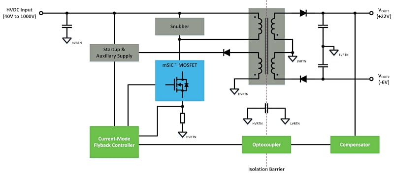
Figure 2. Block diagram of wide input voltage and dual output converter. Image used courtesy of Bodo’s Power Systems [PDF]
Designing for the wide input voltage range presents challenges specifically to the transformer, snubber, control and stability designs. The reference design balances several competing design goals to achieve optimal performance. Important technical aspects addressed in the reference design relate to the transformer structure and construction, snubber circuit and controller. The design provides reliable controllability at both extremes of the input voltage range and ensures a stable output under fast, dynamic line and load conditions.
In conclusion, the design and implementation of a low-power auxiliary power supply within traction inverters are critical for ensuring the functional safety of electric vehicles. The use of flyback converters to convert a high-voltage DC input to low-voltage DC outputs provides a robust backup power solution during fault conditions. This redundancy is essential to maintain vehicle controllability and meet the stringent safety goals for compliance with ISO 26262 standards.
The integration of SiC MOSFETs in the auxiliary power supply further enhances the system’s capability to handle high voltages and ensures safe operation under various fault scenarios. By understanding the operating conditions of electric machines and the importance of maintaining a safe state during faults, engineers can design more reliable and safer auxiliary power supplies for traction inverters for electric vehicles.
This article originally appeared in Bodo’s Power Systems [PDF] magazine.
Related Content