Facebook
 Google
 GitHub
 Linkedin
Evaluating the Effect of High Switching Frequency on the Performance of an Active Front End Converter
This article features the benefits of operating at high frequencies and the impact of dead-time and inductance value on both operation and control of AFE.
Increasing the switching frequency of a power converter will bring a number of benefits; passive component size can be reduced as the requirements for stored energy decrease, and increasing control loop bandwidths will enhance dynamic performance. For commercial power converters operating in the 10s of kW though, the upper limit of switching frequency has tended to be in the 10 – 20 kHz region where IGBT switching losses start to become unmanageable without more complex soft switching techniques.
Introduction
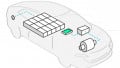
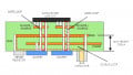
With the recent rise of wide-bandgap semiconductors, particularly Silicon Carbide (SiC), switching losses have once again taken a back a seat and the frequency of converters can be pushed further, but is there a point at which other system-level challenges limit performance? The Converter Technology Hardware Stack™ has been used to explore the behaviour of a 10 kW active front end (AFE, Figure 1) as a function of switching frequency and highlight some of the challenges seen when running at high frequency with this topology.

Figure 1: (i) Converter Technology Hardware StackTM Rapid Prototyping System (ii) 10 kW Active Front End Schematic and Parameters
Control of the AFE
An AFE is a natively bidirectional power topology which allows a three-phase AC supply to be converted to a high voltage DC-link whilst maintaining excellent power factor and low harmonic distortion. Rather than adhering to the methods used in single-phase PFC, whereby the mains current is forced to follow the shape of the mains voltage, mimicking a perfectly resistive load, most three-phase PFCs operate slightly differently. The central premise can be most readily understood if a single phase of the converter is analyzed and imagined to be running as an inverter from a constant DC link. A duty cycle is chosen so that a sine wave of almost identical phase and magnitude to the mains is generated at the converter side of the input inductors. Adjusting the magnitude and phase of the converter voltage, VAFE, relative to the input voltage, VIN, will create a voltage drop across the inductor, forcing current to flow. By adjusting the amplitude and angle of the current relative to the input voltage, full bi-directional control of both active and reactive power becomes relatively simple to implement, opening up the converter to run in regenerative mode and/or carry out reactive power compensation. Figure 2 demonstrates the calculation of the converter voltage VAFE and phase angle ε (ignoring the impact of inductor ESR for clarity). For 10kW total power (3.3kW/phase, power flow from AC to DC link), 230Vrms phase voltage, 50Hz mains, unity power factor and a 1mH inductor, calculations show that VAFE will need to be around 230.05Vrms and lag the mains voltage by 1.13°.

Figure 2: Calculating the Converter Voltage and Phase Angle
For this converter, Voltage Oriented Control (explained in some detail in [1]) is used to accomplish this. In brief, the three-phase rotating values for input voltage and current are transformed into stationary values within a DQ reference frame aligned to the phase of the input voltage. In this way, simple PI controllers can be used to independently set the active and reactive current flow through the inductor. An outer loop is then closed around these to regulate the DC link voltage.
The Influence of the Inductor Value
In general, an increase in switching frequency allows for a corresponding decrease in inductor for a given ripple current, but there are other considerations when using an AFE. In assessing whether the inductor value can be reduced, one has to consider not only the current ripple but also the resolution of the measurement data available and the potential impact on system stability. As can be seen from the calculations in Figure 2, the required AFE voltage and angle are very close to the phase voltage, and both are directly related to the impedance of the inductor at line frequency. Whilst a simple voltage transducer with a measurement accuracy of 1 % would cause no issue when measuring the DC output voltage of the converter, it becomes significant when looking at the input voltage.
It should also be considered that by setting the voltage VAFE relative to a measured input voltage to force current flow through the inductor, the current controller is essentially closing the loop around the inductor, so the gain of the system is inversely proportional to the inductor value. Combining the increased impact of measurement inaccuracies with extra sensitivity suggests that targeting very high-frequency operation (100s of kHz) to use lower inductance at these power levels would likely require more complex control schemes.
Operational Data

Figure 3: Efficiency of a 10 kW Active Front End vs Switching Frequency
The converter was run at switching frequencies from 30 – 100 kHz and at loads of 10 – 100 %. Input voltage was 230Vrms(ph) and output was 800Vdc. Input and output power were monitored to calculate efficiency whilst the power factor and THDi were directly available from the power analyser on the input. Figure 3 shows the variation of efficiency of the converter over the whole range of conditions. As can be seen, even in this prototyping setup, efficiencies above 98 % are achievable. The maximum full load efficiency was measured at 98.6 % when running at 50 kHz.
Whilst it is common to use the power factor as a figure of merit, IEC Standard 61000-3-2 actually dictates maximum limits of harmonic distortion in the current waveform when determining EMC compliance. Although compliance can only truly be assessed by looking at the current harmonics individually, a rough guide is that THDi should be less than 10% (the sum total of all of the stated harmonic limits). For reference, this would equate to a power factor of 0.995 on a system where the voltage and current are perfectly in phase.

Figure 4: V_out and I_ph at Fs = 50 kHz, Pout = 10 kW, Dead Time = 200 ns. Efficiency = 98.6%, THD_i = 3.2%
THDi was seen to reduce with an increase in switching frequency. Running the AFE at a switching frequency of 50 kHz presents a THDi of just 3.2% and the THDi was observed to be less than 5% across the range of switching frequencies tested, though there was a slight drop off in performance above 80kHz.
The Impact of Dead-Time
The drop off in efficiency and harmonic performance at high frequency are likely both attributable to the increasing impact of dead time. As demonstrated in [2], the error in the duty cycle when a sine wave is generated by an inverter power stage is directly proportional to the dead time divided by the switching period. This causes deformation of the waveform, which gets exaggerated at higher switching frequencies. This distortion causes the waveform to contain more low order odd harmonics, causing THDi to increase. This can be seen from the simulation results shown in Figure 5.

Figure 5: Simulating the Effect of Dead Time on AFE Currents
The less immediately obvious impact is how this affects the losses. During the dead time period, circulating current will be forced to flow through the diodes rather than the MOSFETs. The MOSFET in this package has a very low RDS(on) of 25 mΩ whereas the diode is less optimised and has a typical forward voltage of 1.5 V. By forcing the current to spend more time flowing through the comparatively lossy diodes instead of the MOSFETs it is inevitable that the power loss of the system will go up.
Conclusions
One of the key benefits of operating at high frequencies is the ability to reduce the size of magnetics. The impact of the inductance value on both the operation and control of the AFE has been demonstrated, highlighting the complications that arise when increasing switching frequency in an attempt to minimise the inductance value.
It has also been shown that dead time directly impacts the both the generated waveform shape and the distribution of losses throughout the power devices so should be considered when determining the operating frequency and even when assessing semiconductors. Although dead-time is important for safe operation of the converter, the loss incurred in the diodes during the dead-time period could become a factor when targeting ultra-high efficiencies (>99%).
Using the Hardware Stack to investigate the operation of an AFE over a wide range of frequencies gave 50 kHz as the optimum switching frequency for this converter, resulting in an efficiency of 98.6 % and a THDi of 3.2% at full load. This was achieved without optimisation of magnetics, implementation of specialised modulation patterns or the use of proprietary control algorithms. The fact that there are demonstrable, explainable upper limits to the switching frequency at which the efficiency and power factor both start to decrease should not dissuade us from pushing the limits of high-frequency operation but be used alongside other considerations to make an informed decision on the operating window of the converter design.
About the Author
Jon Woodhead works as the Senior Designer at Converter Technology Ltd., Pangbourne, UK, where he is responsible for the design and development of power converters and cover any or all areas of the complete design cycle: Research, Circuit/System Design to Specification, Schematic capture, PCB layout, Prototyping, Lab Test/Development and EMC Testing/Standards Compliance. He earned his degree in Electronic and Electrical Engineering at Loughborough University located in Loughborough, England. He then acquired his Master's of Science in Power Electronics at Nottingham University, England.
References
- S. L. Sanjuan, “Voltage Oriented Control of Three-Phase Boost PWM Converters,” 2010. [Online]. Available: http://webfiles. portal.chalmers.se/et/MSc/SylvainLECHATSANJUANMSc.pdf. [Accessed 1 February 2017].
- I.D.Mosely, P.H.Mellor and C.M.Bingham, “Effect of Dead Time on Harmonic Distortion in Class-D Audio Power Amplifiers,” Electronics Letters, vol. Vol. 35, no. No. 12, 1999.
This article originally appeared in the Bodo’s Power Systems magazine.