Facebook
 Google
 GitHub
 Linkedin
7th Gen Fast Recovery Diode Enabling Full Performance of Modern IGBTs
With 7th gen IGBTs, switching speed limits shift from the transistor to the fast recovery diode. As IGBTs improve, this diode becomes the key component defining operating limits.
This article is published by EEPower as part of an exclusive digital content partnership with Bodo’s Power Systems.
With the rise of 7th generation IGBTs, power electronics designers are facing a new reality: switching speed is no longer limited by the transistor itself but increasingly by the fast recovery diode. As IGBT technologies push toward steeper di/dt, lower gate resistance, and reduced switching losses, the diode becomes the decisive component that defines operating limits.
Why the Fast Recovery Diode Can Become a Performance Limiter
In hard-switched converter topologies, the turn-on of the IGBT is inseparably linked to the reverse recovery behavior of the fast recovery diode. Any abrupt interruption of reverse current results in voltage overshoot, higher electromagnetic interference (EMI), and increased stress on the anti-parallel IGBT chip.

Image used courtesy of Freepik
With earlier IGBT generations, conservative gate driving often masked diode limitations. In contrast, modern 7th-generation trench IGBTs are capable of extremely fast current commutation, making them highly sensitive to diode behavior, particularly at low forward currents and high junction temperatures.
Soft recovery diodes like the Controlled Axial Lifetime (CAL) diodes from Semikron Danfoss are a perfect option to limit voltage overshoot and enable higher switching speeds without the need for excessive gate resistance or snubbing circuits.
The CAL Concept: Controlled Axial Charge Carrier Distribution
The CAL diode concept is designed to limit voltage overshoot via a clever device structure utilizing semiconductor physics. Instead of solely on bulk lifetime killing, CAL diodes use an axially tailored lifetime profile (Figure 1). Charge carrier lifetime τ is intentionally reduced close to the p-n junction to minimize the reverse recovery charge Qrr and recovery peak current IRRM. The base lifetime in the n- region is higher and is complemented by a tailored buffer zone at the n-]/n+ interface.
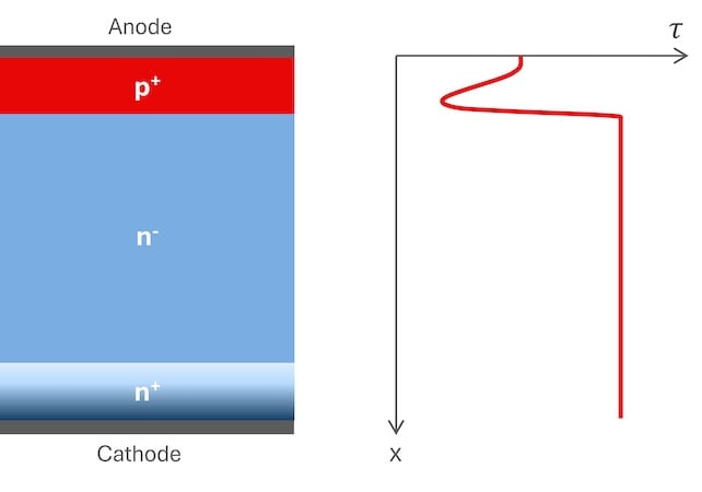
Figure 1. CAL diode structure and charge carrier lifetime. Image used courtesy of Bodo’s Power Systems [PDF]
During reverse recovery, this lifetime profile promotes a controlled overlap between the rising voltage and a residual tail current. As sufficient charge carriers remain in the n-region, the reverse current decays smoothly instead of abruptly. This prevents snap-off behavior, reduces current transients, and consequently limits voltage overshoot caused by circuit inductances.
Overvoltage Behaviour
One of the defining characteristics of the newest 7th–generation CAL diode is its low dynamic overvoltage, enabled by an exceptionally soft reverse recovery behavior. The CAL7 maintains its softness across the entire operating range. For the system designer, this translates into greater freedom in gate driver tuning. Reduced reverse recovery stress allows higher turn-on di/dt, which reduces IGBT switching losses. At the same time, the soft recovery behavior mitigates voltage overshoot and high-frequency oscillations, helping to control EMI.
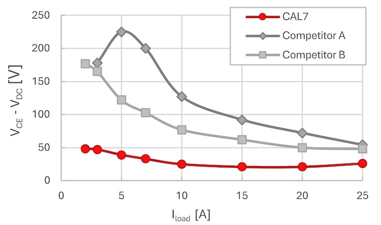
Figure 2. Overvoltage vs. load current – Benchmark. Image used courtesy of Bodo’s Power Systems [PDF]
Benchmark measurements (Figure 2) show that CAL7 generates significantly lower switching overvoltage VCE – VDC than competitor fast recovery diodes under identical commutation conditions: RGon = 1Ω, di/dt = 4kA/µs, VDC = 900V, Tj = 150°C.
Thin Wafer Enables Higher Current Density and Power Cycling Durability
CAL7 is the first CAL diode generation from Semikron Danfoss, manufactured using thin wafer silicon technology. This innovation brings two decisive advantages. First, the reduced silicon thickness enables a lower forward voltage and a significant increase in current density, more than 25% compared to CAL4. This allows higher current ratings within the same chip footprint, supporting a higher power density at the module level.
Second, thin wafer technology reduces thermomechanical stress during operation. Lower silicon stiffness results in reduced strain on solder joints and bond wire connections during temperature swings, leading to markedly improved power cycling capability. Tests indicate lifetime improvements of 30% compared to previous generations.
Cosmic Ray Robustness
As blocking voltages increase, cosmic ray-induced failures can become a non-negligible reliability concern, especially in high-power, high-voltage converters operated at altitude or over long lifetimes.
Fast recovery diodes often exhibit lower tolerance to cosmic radiation than IGBTs, making them the weak link in module robustness. CAL technology has historically addressed this issue, and CAL7 continues this tradition.
Although the move to thinner silicon slightly reduces absolute margins compared to CAL4, CAL7 still delivers best-in-class cosmic ray failure rates, outperforming competitor fast recovery diodes by orders of magnitude (Figure 3). At application‑relevant voltages, CAL7 exhibits extremely low FIT rates, ensuring highly reliable operation with negligible impact from cosmic ray-induced failures.
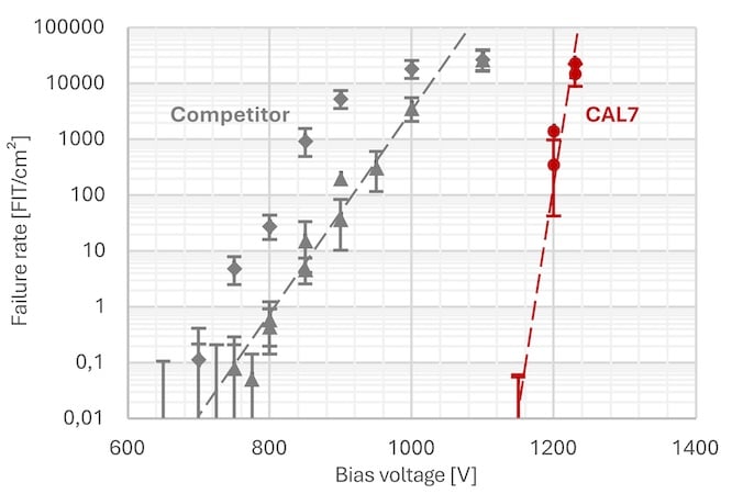
Figure 3. Cosmic ray FIT rate vs. Bias voltage. Image used courtesy of Bodo’s Power Systems [PDF]
Cornerstone of New Medium Power Module Platforms
CAL7 diode technology is a key building block in Semikron Danfoss’ next generation of power modules. Compared to earlier CAL generations, it achieves significantly lower forward voltage, improving overall efficiency without sacrificing softness.
CAL7 has been optimized for a typical switching frequency range up to 10 kHz, relevant for most industrial applications. Like previous generations, it exhibits a positive temperature coefficient of forward voltage, facilitating safe paralleling of devices and stable current sharing.
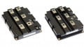
The CAL7 diode generation will first be integrated into Semikron Danfoss’ new medium power module platforms
- SEMITRANS 3+, extending the platform to a market-leading 1000A / 1200V variant in a 62mm form-factor
- SEMiX 3p+, enabling new 1200V high-power variants up to 900A
- SEMITRANS 20, roll-out of 1200V platform with ratings ranging from 1200A to 1800A
Power Loss Comparison
In the following section, a UPS application example for a three-level TNPC topology of SEMITRANS 3+ 800A 1200V with 7th-generation IGBT is provided and compared in terms of power losses for CAL7 vs. CAL4 diode variants. The calculation was performed via Semikron Danfoss’ customer simulation tool SemiSel with the following application parameters: VDC = 740V, Iout = 300A, fsw = 6kHz.
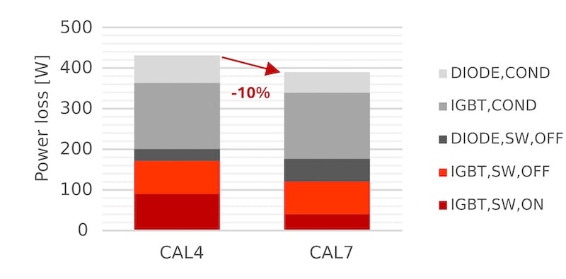
Figure 4. Power factor +1 loss comparison. Image used courtesy of Bodo’s Power Systems [PDF]
In inverter operation (Figure 4) the IGBT switch-on losses can be reduced significantly by 55% with the CAL7 module variant due the faster IGBT current rise enabled by lower gate resistance. This results in an overall loss reduction of around 10%, improving the inverter efficiency by 0.1%.
In active front-end operation (Figure 5), the overall losses can be reduced by 16% with the CAL7 module variant due to its significantly lower forward voltage and the ability to reduce IGBT switch-on losses.
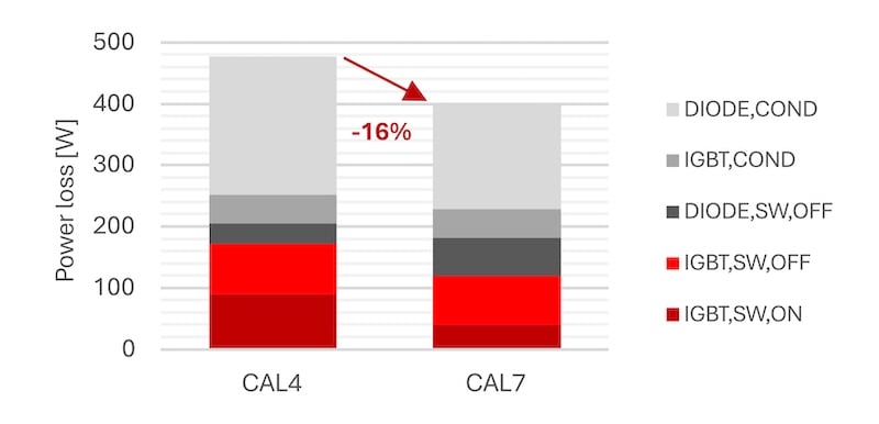
Figure 5. Power factor -1 loss comparison. Image used courtesy of Bodo’s Power Systems [PDF]
In both operative modes, the overall loss reduction of the CAL7 module variant lowers the requirements towards the cooling setup or enables up to 10% higher output power within an existing cooling setup.
Conclusion: Softness as Competitive Advantage
As power electronics enters an era defined by high power density, fast IGBT switching enabled by soft diode behavior has become a decisive differentiator. With CAL7, Semikron Danfoss delivers a fast recovery diode that sets benchmarks where it matters: best-in-class low overvoltage through exceptional softness and industry-leading cosmic ray robustness bundled with high current density.
This article originally appeared in Bodo’s Power Systems [PDF] magazine.