Facebook
 Google
 GitHub
 Linkedin
TDK Augments its Line of High Current Flat Wire Inductors
The new compact SMT power chokes feature inductances ranging from 1.0 to 30µH and saturation currents extending from 10.3 to 40.4 ADC
The B82559B*A019 series replaces TDK’s B82559A*A016 series and take up 12% less precious board space.

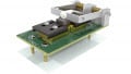
Image courtesy of TDK
TDK’s ten member B82559B*A016 series represent the latest addition to the company’s line of EPCOS ERU SMT power inductors. Notable for their small size, the new units take up 17.3 x 16.5 mm of board space. Insertion heights are 7.55mm from 11.1mm, with heights varying with inductances.
The low profile of this series of inductors is made possible by its flat rectangular helical winding technology. Flat windings serve to lower losses within the inductors, and also to lower DC resistance, which for the B82559B*A016 series are from between 1 and 15.4 milliohms.
TDK mentions the devices are “easily customized.”
Construction Specifics for the B82559B*A016 Series
- The units are magnetically shielded
- High temperature ferrite core
- Helically wound
- A third pin for solid overall system reliability
- Underbody termination
- Self-leaded construction
- Terminals are lead-free and tinned
Specification for members of the B82559B*A016 series
The inductances stated in the second column in the table are measured at 100 kHz, 0.1 V, +25 °C. The inductance tolerance is ±10%. DC resistance is measured at +25 °C, also with a tolerance of ±10%.
|
Series Member |
Inductance µH |
ISAT @25℃ Amperes |
ISAT @100℃ Amperes |
IR Amperes |
RDC mΩ (typical) |
Height mm |
| B82559B2102A016 | 1.0 | 40.4 | 34.4 | 36.0 | 1.0 | 7.20 |
| B82559B3152A016 | 1.5 | 40.5 | 35.3 | 30.0 | 1.4 | 8.10 |
| B82559B4222A016 | 2.2 | 37.3 | 31.8 | 26.8 | 1.8 | 9.10 |
| B82559B5332A016 | 3.3 | 30.9 | 26.5 | 25.0 | 2.2 | 10.0 |
| B82559B5472A016 | 4.7 | 21.3 | 18.9 | 25.0 | 2.2 | 10.0 |
| B82559B6682A016 | 6.8 | 18.7 | 16.0 | 14.4 | 6.2 | 8.10 |
| B82559B7103A016 | 10.0 | 14.6 | 12.8 | 13.0 | 7.2 | 8.10 |
| B82559B0153A016 | 15.0 | 14.0 | 12.1 | 11.7 | 10.2 | 9.10 |
| B82559B0203A016 | 20.0 | 12.4 | 10.8 | 10.0 | 12.1 | 10.0 |
| B82559B0303A016 | 30.0 | 10.3 | 9.1 | 8.5 | 15.4 | 10.75 |
Saturation Current: Current that will cause an approximately 20% drop in the inductance
Rated Current: Current that will cause a change of 40°K of self heating measured from room temperature
Inductance vs. Load Current
The relationship between current, inductance and self heating is of critical importance to designers. These relationships are separately graphed for each of the ten members of the new series in the data sheet.
The temperature rise vs. current is measured from a base of 25℃, with the measurement being made after current is applied for one half of an hour. This measurement is made on the top of an inductor that has been mounted on a PCB, with no forced air cooling.
For inductance vs. current, the curves are plotted at 25℃ and 100℃.
Applications
- Storage and output chokes for point of load (POL) converters
- High current switch-mode power supplies (SMPS)
- DC/DC converters
- EVs and hybrid vehicles
- Inverters for photovoltaic systems
- Voltage regulator modules (VRM)
Physical Considerations
- B82559B*A016 series operate over a range of -40 to +150 ℃.
- The units weigh between 6.8 grams (1.0µH) and 10.5 grams (30.0µH)
Regulatory Concerns
- AEC-Q200 qualified
- RoHS-compatible