Facebook
 Google
 GitHub
 Linkedin
Pulsed Inductance Measurement on Low-inductance, High-Current SMD Inductors
PCB-mounted SMD and THD inductors are often specified. These measurement voltages are superimposed on a direct current to characterize the inductance's saturation behavior. In contrast, the pulse method of the Power Choke Tester DPG10 series uses an application-related voltage curve shape and amplitude. This article presents and compares both measurement methods.
This article is published by EEPower as part of an exclusive digital content partnership with Bodo’s Power Systems.
The pulse measurement method of the Power Choke Tester DPG10 series has advantages over other methods of inductance measurement. It can be used from small, PCB-mounted inductors to inductors weighing several tonnes. With the help of new test adapters, SMD inductors down to 50 nH with currents of up to several 100 A can now be tested more easily and realistically than with LCR meters.
PCB-mounted SMD and THD inductors are often still specified in the data sheets with small-signal measurements of sinusoidal voltages and currents in the mV and µA range (LCR meter). These measurement voltages are superimposed on a direct current to characterize the inductance’s saturation behavior. In contrast, the pulse method of the Power Choke Tester DPG10 series has significant advantages, as it uses an application-related voltage curve shape (squarewave) and amplitude (several V to several 100 V).
This article presents and compares both measurement methods. The problems with measuring small inductance values (< 1 µH) are explained, and the new test adapters for SMD inductors down to 50 nH are presented.

Figure 1. Image used courtesy of Bodo’s Power Systems [PDF]
Pulse Measurement Principle of the Power Choke Tester DPG10/20 Series
The pulse measurement principle of the DPG10 series works with a single squarewave voltage pulse. The amplitude can be set in a wide range from < 10 V to 400 V. It should be selected to correspond approximately to the voltage at the inductor in the real application.

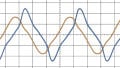
Figure 2. Test pulse of the Power Choke Tester DPG10 CH3: 5V/div CH4: 20A/div Time base: 2µs/div. Image used courtesy of Bodo’s Power Systems [PDF]
This results in a ramp-shaped current curve in the test specimen. The current-dependent differential inductance Ldiff(i) and several other variables can then be calculated from the slew rate di/dt, considering the ohmic resistance R.
When the preset maximum current or preset pulse duration is reached, the measuring pulse is switched off again.
From the curve of the current i(t) and the voltage v(t) on the test specimen, the following variables can be calculated with a single test pulse:
- Differential inductance Ldiff(i) and Ldiff(∫Udt)
- Amplitude inductance Lamp(i) and Lamp(∫Udt)
- Linked flux ψ(i)
- Magnetic co-energy Wco(i)
- Flux density B(i), if the core cross-section and number of turns are known
The behavior of all core materials is more or less dependent on frequency and amplitude. Since the test pulse has the same rectangular curve shape as in most power electronics applications and the same amplitude and frequency or pulse width as in the real application, the most realistic measurement results are obtained. The small-signal measurement of LCR meters, on the other hand, is based on measurement signals that often do not match real conditions. In these cases, the results are not very meaningful.

Figure 3. Diagram of the differential inductance Ldiff(i). Image used courtesy of Bodo’s Power Systems [PDF]
The pulse voltage source takes the pulse energy from a capacitor bank charged to the desired measurement voltage. Its energy content is usually significantly higher than the energy withdrawn during the pulse. The voltage of the test pulse is then roughly constant, although this is not a necessary condition. Due to the principle, there is no upper limit for the capacitance of the capacitor bank, regardless of the type of test specimen. That is one of the reasons for the extremely wide application range of the Power Choke Tester DPG10/20 series for virtually all inductive power components, from small PCB-mounted inductors to inductors weighing several tonnes in the MVA range.
Advantages of the DPG10/20 measurement principle
- Enormously wide range of applications
- Very wide current range, available from 10 mA to 10 kA
- Pulse energy available from several µJ to 15 kJ
- Suitable for all core materials from 1 MHz to < 0.5 Hz
- Small, light, and relatively inexpensive despite the very high test currents
- Very easy to use, measurement results within seconds
- No thermal influence on the test specimen
Application examples
- Storage chokes for switch mode power supplies, DC/DC converters, etc.
- Filter chokes for UPS, inverters, etc.
- Mains chokes for PFC, etc., and commutation inductors
- Suppressor chokes and current-compensated chokes
- Coils of electromagnets, valve actuators, etc.
- Transformers for flyback converters
- Other transformers and motors
- Many other inductive power components
Small-Signal Measurement Principle of LCR Meters With DC Bias
LCR meters use sinusoidal voltages and currents with selectable frequencies in the mV to µV and mA to µA range, superimposed on an adjustable direct current. The inductance, resistance, and Q factor can then be calculated from the amplitude and phase angle of the voltage and current through the test specimen.

Figure 4. Small-signal measurement of LCR meters (auto-balancing method). Image used courtesy of Bodo’s Power Systems [PDF]
Such a modulation of the core material with tiny hysteresis curves around an operating point cannot be found in switch mode power electronics applications. The test result of such a small-signal measurement is not very meaningful. The difference between these measurement results and the DPG10/20 pulse measurement method depends greatly on the core material and cannot generally be stated for an entire group of materials. In some cases, the differences are relatively small, while in others, they can be considerable.
Due to the large DC bias units required, this method is restricted to low measuring currents of up to 250A and requires very expensive test equipment.
Many individual measurements must be carried out to create a complete measurement curve L(i). This takes a relatively long time and places a thermal load on the test specimen. In the overload range, this can make the measurement of the saturation behavior impossible due to excessive heating. At least the behavior cannot simply be measured at defined temperatures because the self-heating determines the temperature.
On the other hand, the pulse measurement method does not lead to any measurable heating of the test specimen because of the short pulse duration. The behavior can thus be determined at any desired temperature, for example, in the climate cabinet.
Advantages of the pulse measurement principle compared to small-signal measurement with DC bias unit
- Realistic measurement principle
- Significantly higher test currents are possible
- Significantly lower equipment costs
- No thermal influence on the test specimen, as the measuring pulse is very short (µs to ms)
Measurement Adapter for Measuring Low-Inductance SMD Components up to 50 nH
Precise inductance measurement of low-inductance components < 1 µH is fundamentally problematic, error-prone, and metrologically demanding, regardless of which measuring device and which measurement principle is used. In the pulse measurement principle of the Power Choke Tester DPG10 series, it is the parasitic inductances, the inductive coupling between the force leads and the sense leads, and the maximum sampling rate that are important for an accurate measurement result.
Together with the test specimen, the parasitic inductance of the test leads, as well as the device’s parasitic internal inductances, form an inductive voltage divider. If these parasitic inductances are larger or even much larger than the inductance of the test specimen, then only a small part of the voltage of the test pulse is dropped across the test specimen. Most of it is then dropped across the parasitic inductances. Although a 4-wire measurement is always carried out, this reduces the measuring accuracy. In the 4-wire measurement, the voltage is tapped directly on the test specimen via separate sense leads.
To prevent inaccurate measurement results, measurements must be discarded if too much pulse voltage drops across the parasitic inductances. Therefore, the parasitic inductances must be minimized to measure the smallest possible inductance values.
The test leads play a significant role in parasitic inductances. An ideal test lead made of highly flexible measuring litz wire with a 6mm² copper cross-section and a length of 0.6m already has an inductance of over 700 nH. In conjunction with further parasitic inductances for the crocodile clips on the test specimen and the device’s internal inductances, this limits the measurement to 500 nH at best.
To extend the DPG10 series’s area of use down to 50nH, ed-k has developed new solderless Kelvin test adapters for SMD components that can be plugged directly into the sockets on the front panel of the devices without the use of test leads. Thus, the influence of the test leads can be eliminated. These test adapters are optimized for minimum parasitic inductances. In conjunction with the optimum internal design of the DPG10 series and the associated extremely low parasitic inductances, measurement can be performed in some cases down to 50 nH.
The Kelvin test adapters MABxSMD are plugged directly into the front panel. There is a separate test adapter (MAB1SMD, MAB2SMD, or MAB3SMD) for each of the three measuring ranges of the DPG10 series. The test adapters can accommodate SMD components contacted on the underside with a width of 5-25 mm, a length of 5-25 mm, and a height of up to 25 mm. After positioning, the test specimen is held in place by a spring-loaded bracket, which makes handling easy.
Measurement Examples
Figures 5-8 show measurement examples of SMD inductors from the catalog range of various manufacturers.

Figure 5. Rated inductance 200 nH, thermally rated current 92 ARMS. Image used courtesy of Bodo’s Power Systems [PDF]
Figure 5 shows the differential inductance Ldiff(i) of an inductor with EP ferrite core and air gap determined with the Power Choke Tester DPG10-1000B and the Kelvin test adapter MAB1SMD. According to the datasheet, the saturation current with a 20% drop in inductance is 113 A, and the thermally permissible RMS current is 92 A. The rated inductance of 200 nH, according to the datasheet, is not quite achieved (194 nH). However, the saturation current is significantly higher than specified (approx. 150A).
There are several reasons for these differences.
Firstly, there are the different measurement methods. As previously explained, the Power Choke Tester DPG10 series uses application-oriented squarewave large-signal measuring pulses with the same amplitude as in the real application. The small-signal modulation of the core material with sinusoidal voltages in the µV or mV range and currents in the µA or mA range provide different results depending on the core material.
However, with such extremely small inductance values, even the smallest differences in the geometry of the test setup play a role that cannot be neglected. Even small deviations in the test point on the component or the type of current feed (e.g., planar or punctiform) can lead to different measurement results. To obtain reproducible test results, the geometry of the test setup must always be the same. This can hardly be guaranteed without special test adapters and applies not only to the pulse measurement principle but also in the same way to small-signal measurements with LCR meters.
Last but not least, specimen scatter of up to 10% must also be taken into account.
The inductor in Figure 6 in a 5050 package consists of a powder core material with a distributed air gap. The nominal value of 220nH is exceeded at the beginning (280 nH). The thermally permissible RMS current is specified at 66 A, and the saturation current with a 20% drop in inductance is specified at 68 A.
The same reasons apply to the differences between the pulse measurement and the datasheet specifications as in the previous example. The data sheet specification for L0 (220 nH @ 100 kHz, 0.25 V) cannot be reproduced with an LCR meter without a special test adapter. This is difficult even with a carefully calibrated test adapter. The actual initial inductance L0 appears to be systematically greater than specified, which is confirmed by the measurement with the Power Choke Tester DPG10.

Figure 6. Rated inductance 220 nH, thermally rated current 66 ARMS, 5050 package. Image used courtesy of Bodo’s Power Systems [PDF]
The saturation curve of the powder core material is much softer than that of ferrite cores with an air gap. As a result, this core material is less problematic when used in switch mode applications if the current rises far above the rated current in the event of a fault. Even at 200 A, this specimen still has an inductance of over 140 nH.
These statements also apply analogously to the inductor in Figure 7. It has a rated inductance of 470 nH with a thermally permissible RMS current of 30 ARMS in the 4040 package (10 x 10 x 4 mm³) and consists of the same core material.

Figure 7. Rated inductance 470 nH, thermally rated current 30 ARMS, 4040 package. Image used courtesy of Bodo’s Power Systems [PDF]
The last measurement example in Figure 8 is a small SMD inductor with dimensions of 8 x 8 x 4 mm³. It is also a powder core with a distributed air gap. In this case, the measured values slightly deviate from the data sheet specifications due to component scatter (inductance at 3.2 A 28.6 µH, data sheet specification 26.4 µH). Measuring such large inductance values is much less critical and less prone to error.
Correct Choice of Measurement Parameters
At very low inductance values, both measurement parameters—test current and test voltage—can no longer be freely selected. This is due to the minimum pulse duration of 3 µs of the Power Choke Tester DPG10 series. The test pulse duration can be roughly estimated using the following formula:
\[\Delta\,t=L_{diff}*\Delta\,i/V\]
The formula states that the smaller the inductance, the smaller the test current, and the greater the measurement voltage, the shorter the pulse duration. At very low inductance values, the test voltage must be as low as possible and the test current as high as possible. The smallest presettable test voltage is 10 V, although the effective test voltage can be as low as 6-8 V due to parasitic voltage drops at higher currents.

Figure 8. Rated inductance 33 µH, thermally rated current 3.1 ARMS, 3232 packages. Image used courtesy of Bodo’s Power Systems [PDF]
This results in the following minimum required test currents for a given inductance:
- 100 nH => approx.
- 150 A 1 µH => approx. 20 A
- 10 µH => approx. 3 A
However, components with a significantly lower rated current can usually be measured by selecting a correspondingly higher test current until a measurement is possible. As the test pulse is extremely short, a multiple of the rated current does not lead to any heating or damage to the component.
Takeaways of the Pulse Measurement Method
Precise inductance measurement of low-inductance components < 1 µH is fundamentally problematic, error-prone, and metrologically demanding.
With the new test adapters, the inductance L(i) of SMD inductors down to 50 nH can be measured more easily and realistically than with LCR meters.
The pulse measurement method enables significantly cheaper measuring equipment, especially for currents above 20 A.
Hopefully, the small-signal measurement method still often used for PCB-mounted inductors will be replaced by a more realistic specification using the pulse measurement method, which uses squarewave pulses with an amplitude close to the applications.
This article originally appeared in Bodo’s Power Systems [PDF] magazine.