Facebook
 Google
 GitHub
 Linkedin
High-Current EMC Filter Enhances 3-Phase System Reliability
EMI Solutions’ EMC filter improves the attenuation of conducted interferers from mains power for photovoltaic inverters, industrial power supplies, and power drive systems.
EMI Solutions (EMIS) is introducing the chassis-mounted MF423-3-3D-BB three-phase EMC filter series designed for high-current, three-phase industrial applications, such as photovoltaic inverters, wind turbines, and industrial motor drives.
The filter connects to the equipment’s mains side via busbar terminations and is designed to enhance the downstream equipment’s immunity from common mode and differential conducted interfering signals.
The EMC filter is specified to operate at the standard 50/60 Hz mains voltage of 440 to 520 VAC, supporting application current levels up to 1000 A.
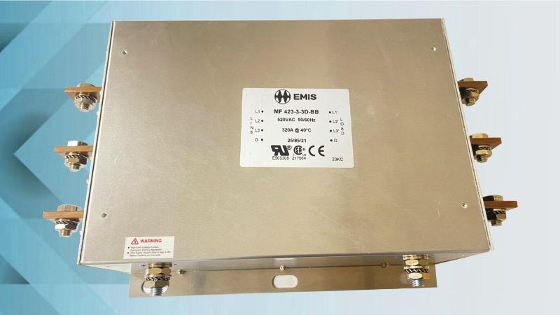
High-current, three-phase EMC filter. Image used courtesy of EMIS
AC Mains Conducted Emissions
Within three-phase AC mains systems, conducted interferers are unwanted emissions at frequencies other than nominal 50/60 Hz power (often above 10 kHz). These emissions can corrupt the power signals delivered to downstream industrial equipment, potentially compromising performance. For AC mains, conducted emissions can come from the power generation source or other connected loads bleeding undesired signals into the system. For inverter applications, AC power delivered back to the grid can similarly contain conducted interfering signals.
In both instances, EMI (electromagnetic interference) filters can block unwanted conducted or radiated signals outside of the desired power signal bandwidth (50/60 Hz nominal).
Three-Phase Industrial EMC Filter
The MF423-3-3D-BB is a series of dual-stage, three-phase, high-performance EMC filters using a bookshelf design to attenuate conducted emissions for motor drive and similar three-phase applications. Within the MF423-3-3D-BB, a series of RC, LC, and choke circuits for each power phase attenuate the undesired conducted emissions.
This filter is designed to suppress common mode and differential emissions, primarily at frequencies above 10 kHz.
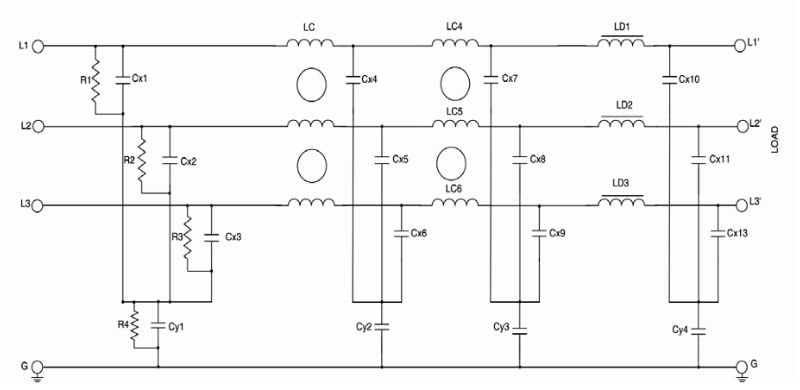
MF423-3-3D-BB EMC filter schematic. Image used courtesy of EMIS
Insertion Loss and EMC Filter Performance
CISPR 17 is the technical standard defining how to test and measure passive EMC filter performance. A key performance metric for an EMC filter is the insertion loss, which is defined as the ratio of the level of the interfering signal at the input of the filter to the level of the signal at the filter output measured in decibels (dB): Insertion loss = 20 log (Signal IN/Signal OUT)
A higher insertion loss indicates that the filter is doing a better job of suppressing the interfering signals.
With a 50 Ω/50 Ω (source impedance/load impedance) test setup, per CISPR 17, the MF423-3-3D-BB has an insertion loss of anywhere between 10 dB and 50 dB for common and differential mode interfering signals between 10 kHz and 1 MHz. This performance is measured with the filter operating at its maximum rated current of 1000 A.
.jpg)
MF423-3-3D-BB EMC filter insertion loss (1000 A). Image used courtesy of EMIS
Filter Physical Properties
The MF423-3-3D-BB series filters are relatively large devices. Each unit is contained in a full metal enclosure, with the highest-rated 1000 A model weighing about 28 Kg.
.jpg)
MF423-3-3D-BB EMC filter dimensions (1000 A). Image used courtesy of EMIS
This model's dimensions are roughly 240 mm x 350 mm, and its height is 170 mm. Large busbar terminals facilitate the connection of the filter between the mains power and the load (or source).