Facebook
 Google
 GitHub
 Linkedin
What is an Electronically Commutated Motor (ECM)?
Learn about the three main components of an electronically commutated motor: a circuit board, an electronic control module, and a three-phase motor.
An electronically commutated motor is a three-phase, brushless DC motor. It comprises three major components: a circuit board, an electronic control module, and a three-phase motor with a permanent magnet rotor, as shown in Figure 1. The module and motor make up the actual ECM. The circuit board is used to set up cooling and heating applications.

Figure 1. Basic components of an ECM. At left is the control module, in the middle is the three-phase stator, and on the right is the rotor, which is pulled out of the motor. Not shown is the circuit board. Image courtesy of RSES
ECM Circuit Board
The circuit board is usually shared by other switches and controls in an HVAC system. There are dip switches and jumper pins on the HVAC system circuit board that allow changes to airflow and comfort options related to ECM operation. The control module is controlled through the circuit board, which has other functions such as controlling the cooling and heating system. Figure 2 illustrates a common circuit board used to control an ECM as well as heating and cooling operations.

Figure 2. The circuit board directs the thermostat, which in turn controls the ECM. This thermostat has dip switches or settings that must be set up to operate the blower based on heating operation and cooling tonnage. Image courtesy of TI
Figure 3 is a close-up of the circuit showing dip switches that must be set in the on or off position per the manufacturer’s recommendations.

Figure 3. Close-up of the circuit showing dip switches that must be set in the on or off position per the manufacturer’s recommendations. Image courtesy of HighPerformanceHVAC
ECM Control Module and Motor
The control module in Figure 4 converts 120-or 240-V single-phase power to essentially three-phase DC power to operate the motor. The control module is a power inverter, which means it converts AC to DC. As shown in Figure 5, the motor appears as if it were a regular motor. The additional length is the electronic module that converts the single-phase alternating current to three-phase direct current power. Figure 6 shows the module and motor connected to the high-and low-voltage wiring.

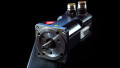
Figure 4. This is a control module that has been removed from a motor. Two sets of wires plug into the side of the module. Image courtesy of RSES

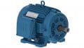
Figure 5. This is a three-phase DC motor. The motor resistance is approximately equal. The resistance is less than 20 ohms between the windings. Image courtesy of RSES

Figure 6. The module section has two connectors. The upper connector is the high-voltage source. The lower connector is the low-voltage control source. The gray section in the upper part of the picture is the motor. The circuit board is not shown but will be connected to the other end of the two connectors. Image courtesy of RSES
In summary, the ECM control converts AC single-phase power to DC power and then pulses that DC voltage appropriately to the three-phase motor windings.
An ECM can change the 60-Hz frequency that controls the speed of the motor. An ECM can control the frequency it delivers to the motor; that is, it is not a slave to the 60-Hz power supplied by the utility company like permanent split capacitor motors (PSC motors) are. Remember that frequency is an integral part of the RPM formula. The lower the frequency, the lower the RPM of the motor speed. As the motor speed decreases, the current draw decreases, making the motor more efficient. An ECM not only operates at lower RPMs than most PSCs, but it is also more efficient at those speeds.
Reasons Why ECMs are Popular
Here are the reasons ECMs are gaining so much popularity among equipment manufacturers:
■ Has high-efficiency operation. ECMs are about 80% efficient when compared to the best PSC motor at 60%. This improves the efficiency rating of a condenser, air handler, or furnace.
■ Adds little heat to the air stream. ECMs run cooler, thus adding less heat to the air circulating through them.
■ Reduces relative humidity in the cooling mode when programmed for lower air speeds and ramping up and down air speeds during the cooling cycle.
■ The ECM starts up slowly, which reduces locked rotor amps and places less stress on the blower wheel, fan blade, and blower housing. This benefit eliminates sudden gusts of air from the duct as well as the abrupt shutdown of airflow at the end of the air cycle. The customer is less likely to notice that the HVAC equipment is cycling on and off. This is a selling point for this type of equipment.
■ Uses standard ball bearings. This makes for long bearing life and the ability to carry heavy loads.
■ Is able to set the motor speed across a wide range of settings for heating, cooling, and condenser pressure.
■ ECMs used as air handlers can be set to operate at a specific CFM. For example, on the circuit board, most ECMs are set up to operate at 400 CFM per ton. A setting of 350 CFM per ton can easily be selected to slow the blower down and allow for more moisture removal when compared to 400-CFM operation. Speeds for condenser fan motors will have a higher CFM rating.
■ Lower air speeds or ramping the airflow up and down traps more dust in the air filter. This makes the air filter more efficient, but it also means that the filter will need to be changed more often. Higher air speeds create more contamination blow by in air filters.
■ Overcomes minor undersized duct designs with greater airflow. The ECM is not designed for this purpose, but it does offer this benefit.
Note:
Do not trust the blower door switch for power disconnection or reconnection. Frequent arcing across the door switch may lead to door switch failure. Use the main disconnect to remove power on any system with an ECM motor before removing or replacing panels with a door switch. Always confirm with a voltmeter that power has been de-energized. Check voltage line to line and each line to ground when you think the power is off. Finally, short the “dead” power to the ground before touching it with your body.
Figure 7 is a flowchart explaining what we discussed in this article. It gives an example of how an ECM motor will operate in an air handler or furnace application.

Figure 7. Flowchart illustrating ECM motor operation in an air handler or furnace application.
The ECM consists of the ECM control module and three-phase motor. Starting at the left side of the flowchart, on a call for heating or cooling, the thermostat closes and completes the circuit to the circuit board in an HVAC system. In most cases, the t’stat is the switch that closes and provides a path for 24 volts to the circuit board. The circuit board is programmed to operate the ECM at a specific CFM or at full speed. Many circuit boards can be set to start the ECM at a low speed and slowly ramp up to the programmed speed over a period of 5 to 8 minutes. The motor will slow down and stop when the thermostat is satisfied, and the fan switch is set to the automatic position.