Facebook
 Google
 GitHub
 Linkedin
What Is Pulse Frequency Modulation?
Every so often, a new data format emerges, and we think it might simply be a typo. Pulse frequency modulation is not new, but many engineers are still unaware of it.
When we use the term ‘PWM,’ most people immediately recognize this as pulse width modulation, the conversion of a 0% to 100% scale of values into a digital value. Only the duration of a pulse needs to be measured to determine the analog value.
PWM is indeed common, and its applications are numerous: from driving motors to simulating varying voltages to small load devices, and even some audio applications where true analog values are difficult or impractical.
However, a related technology is far less known but still somewhat common in application. This is pulse frequency modulation or PFM.
What Is Pulse Frequency Modulation?
Like its common PWM cousin, pulse frequency modulation technology is primarily used to convert a range of signals, called an analog value, into a changing digital measurement that can be captured by even the most basic discrete computers. In this way, it can be used by microcontrollers and industrial controllers (like PLCs) and still be easily adaptable to more advanced industrial computers.

Figure 1. PFM as compared to PWM for low-range and high-range signals. Note that the PWM at the top is a fixed frequency, varying width %, and the PFM at the bottom is a fixed width %, but varying frequency. Image used courtesy of Control Automation
How Is PFM Different From PWM?
The main difference between PWM and PFM is that PWM, since the width of the pulse is changing at a fixed frequency, a timer must be reserved for measuring the duration of the ‘on’ time of the pulse, thus yielding a ‘duty cycle’ percentage, equivalent to 0-100% of the full voltage analog signal. Since the frequency of the signal does not change, only the duration of the ‘on’ time, we have no need to count the number of cycles in a second as it is fixed.
In contrast, the PFM concept varies the frequency of the signal, but each pulse maintains an equal time off and on. This equal on/off pulse is known as a square wave pulse, so we have no need to measure the duration of each pulse. There are two ways to measure a PFM signal, which provides some diversity to the use cases and control theories.
Measuring Overall Pulse Width
First, a timer can be used to measure the total duration of the pulse, and then, in typical electronic math fashion, the inverse of that pulse time can be used to calculate the frequency.
Measuring Pulse Counts Over a Fixed Time
If using a timer to measure each pulse is not practical or impossible, a counter can be used to measure the rising or falling time. The counter sums up the number of pulses over a short time to provide a snapshot of the current frequency.
Both of these strategies–pulse time and pulse count–depend on a known min and max frequency that relate to 0% and 100% of the full-scale real-world value. The max frequency must not be higher than the hardware counter is capable of detecting.
Where Is PFM Used?
One of the major downsides of using PFM is the disruption to nearby applications because the frequency changes through a range. PWM, on the other hand, is a fixed frequency of pulses, so the Hz can be optimized to remove interference with nearby transmission or control equipment.
For this reason, PFM is not used in nearly the quantity of applications as compared to PWM, yet two primary applications dominate its use.

Figure 2. When toroid and ferrite core inductors are used with a very low PWM duty cycle for light loads, they can reduce the efficiency of the supply, capitalizing instead on PFM pulsing. Image used courtesy of Adobe Stock
Power Supplies
First, switch-mode power supplies rely on a pulsing DC output, varying the power output to the load based on the load conditions. This allows heavy loads to receive a more constant energy supply as needed, but lighter loads can consume less power from the source, resulting in a more efficient supply.
However, when the typical PWM is supplied to a light load, the ‘off’ time of the pulse is very long, so the inductor supplying power is able to fully discharge, and the supply capacitor can also discharge, reducing efficiency since it must be recharged before supplying power to the load. To prevent this problem, the PFM model uses a square wave with equal on/off times, so the inductor is never able to discharge, and the supply of current is continuous.
PFM Sensors
Several companies have developed analog-equivalent measurement systems that still use digital qualities. Using PFM and counting edge transitions can consume far less dedicated processing power than running continuous timer tasks, as would be required for PWM.
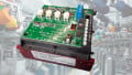
Figure 3. Banner Engineering’s converter from analog to pulsed output signals. Image used courtesy of Banner Engineering
In modern systems, with the variety of both pure analog and advanced protocols like IO-Link, PFM is not seen as a very common solution to the problem of analog signaling, yet some applications (such as Banner Engineering’s S15C system) provide a method of converting between pure analog signals and discrete switched outputs for interface with purely digital controllers.
How Common is PFM?
Once again, this signal switching method is perhaps not a very common pulse train method. Similarities between PWM and PFM can be confusing, but it’s helpful to understand the differences to recognize why PWM has been leveraged in a few key areas of application throughout the industry.