Facebook
 Google
 GitHub
 Linkedin
Navigating Stepper Motor Drive Design
Designing stepper motor drives requires careful consideration of several key factors. This article will help you navigate these considerations and any challenges that may arise during the design process.
Stepper motor drives are essential in producing control signals for precise stepper motor control and motion. To design a stepper motor drive, you must first understand the motor’s characteristics, the drive’s voltage characteristics, and the power electronics.
A power supply is crucial in a stepper motor drive. It provides the necessary current and voltage to drive and control the motor's torque and motion.

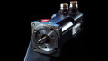
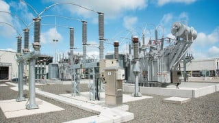
High-precision industrial stepper motor. Image used courtesy of Adobe Stock
Power Supply Considerations
Voltage and current requirements are important in the stepper motor drive design process. The drive must supply the motor windings with enough voltage and current to energize them.
Calculating Drive Voltage
The drive’s voltage should be greater than the stepper motor’s back EMF voltage. Back EMF voltage is generated by the stepper motor during rotation and can be determined using:
\[Back\,EMF=\frac{NX\frac{d\phi}{dt}}{10^{8}}\]
Where N = number of turns in the motor winding
∅ = magnetic flux
t = time in seconds
The motor drive’s voltage rating should be 1.5 to 2 times the stepper motor’s rating. The motor's rating can be obtained by referring to the datasheet.
Calculating Current Rating
The motor drive’s current rating should be equal to or greater than the stepper motor's.
The required current rating can be determined using:
\[Current=\frac{Torque}{2\,X\,\pi X\,Phase\,resistance\,Steps\,per\,revolution}\]
Where torque = torque needed for the application in Nm
Steps per revolution = the number of steps in one revolution
Phase resistance = the resistance in each phase in ohms
The current calculation considers a safety factor of 20-30% of the calculated current rating.
Example calculation:
Consider a motor with the following specifications:
- Rated current: 1.68 A
- Rated voltage: 2.8 V
- Phase resistance: 1.65 Ω
- Required torque: 0.2 Nm
- Steps per revolution: 200
Using the specifications above, the motor drive’s current rating can be calculated as:
\[Current=\frac{0.2\,Nm}{(2\,X\,3.14\,X\,1.65\,\Omega\,X\,200)}=0.00036\,A\]
The required current rating after adding a current factor of 30% is:
\[Required\,Current\,Rating=0.00036\,A+\frac{30}{100}=0.000468\,A\]
Therefore, the current rating of the stepper motor drive must be at least 0.000468 A.
Power Efficiency and Management
Good power management and efficiency are essential to ensuring a stepper motor drive works at high torque with low energy consumption. To improve this power efficiency, a chopper drive converts the DC power supply into a pulsed voltage applied to the stepper motor, making the motor work at a lower voltage, consuming less power and increasing efficiency.
A chopper drive has a duty cycle that can be calculated as:
\[Duty\,Cycle=\frac{Ton}{T}X\,100\%\]
Where Ton is when the voltage is applied to the motor windings and T is the total time in the pulse waveform.
Another method of managing power efficiency is using a micro-stepping drive, which divides every full step of the stepper motor into smaller steps, increasing the accuracy and smoother motion. When choosing a micro-stepping drive, It is important to consider the tradeoff between accuracy and power consumption. The micro-step size can be determined using the formula shown below;
\[Microstep\,Size=\frac{Full\,Step\,Size}{2^{n}}\]
Where n is the number of micro steps per full revolution.
Current limiting and pulse width modulation (PWM) are additional techniques used to improve power efficiency, and PWM can be used to control the amount of power delivered to the motor. The PWM signal’s duty cycle can be calculated as:
\[Duty\,Cycle=\frac{Vmotor}{Vsupply}X\,100\%\]
Where V motor is the voltage required to drive the motor, and V supply is the voltage of the power supply.
Current limiting can prevent the motor from overheating and damaging the drive as a result of drawing too much current. The value of the current limiting can be calculated as:
\[Current\,Limiting=\frac{Vref}{Rsen}\]
Where Vref is the current limiting reference voltage, and R sen is the resistance of the sense resistor.
It is more important to use cooling fans and heat sinks to manage heat dissipation because high current flow over the motor driver can damage the drive and cause the motor to overheat.
The power consumption of the stepper motor drive can be reduced by carefully considering the calculations and formulas involved in power efficiency and management, resulting in increased efficiency and longer motor life.
Power Regulation in Unipolar Stepper Motors
Knowing the stepper motor rating is vital to understanding the power regulator needed. An example of such a power regulator is the 78xx series for smaller unipolar stepper motors. The power regulator also comprises a TIP2955 transistor, where Vcc represents unregulated DC voltage, and Vreg represents regulated voltage.
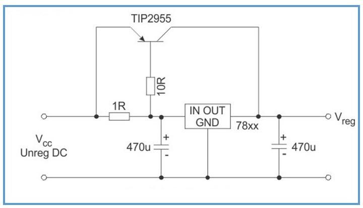
Figure 1. 78xx series voltage regulator for unipolar stepper motor drive. Image used courtesy of Bob Odhiambo
The 78xx series is used in ULN2003 stepper motor drives for unipolar stepper motors with a voltage rating between 5 V and 12 V and a current rating between 200 mA and 400 mA. The regulator should be fixed with a heatsink to dissipate excess heat. The choice of power regulator in a motor drive system depends on the application, drive rating, and stepper motor rating.
ULN2003 Series Stepper Motor Drive
The ULN2003 series is a monolithic Darlington transistor array that can handle high-voltage and high-current applications. The integrated circuit (IC) has transistor pairs, each with a peak voltage rating of 50 V and the ability to handle a continuous current of 500 mA. The ULN2003 series is used in solenoids, relays, and stepper motors (inductive loads) due to the open collector arrangement of the arrays.
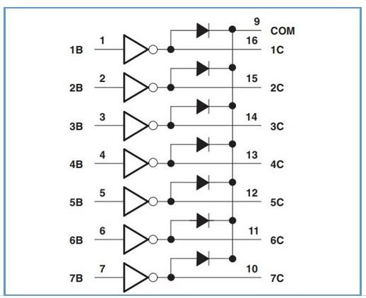
Figure 2. Simple block diagram of ULN2003 series IC. Image used courtesy of Texas Instruments.
In stepper motors, the wires of the four windings are connected to the transistor pairs of the IC, which are energized in the sequence needed. For the control circuit, acceleration and deceleration ramps can reduce noise and vibration in the motor’s rotation.
Related Content