Facebook
 Google
 GitHub
 Linkedin
The Meaning Behind Motor and Multi-Motor Markings
Learn what motor and multi-motor equipment markings required by the National Electrical Code mean.
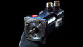
NEC’s Section 430.7 requires marking information on motors. This marking carries valuable figures beyond horsepower, voltage, and speed and is stamped on one or several nameplates.
Image used courtesy of Pixabay
National Electrical Code Section 430.7 Marking
NEC Section 430.7 rules electric motor marking.
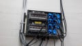
Figure 1 shows the nameplate on a general-purpose electric motor built under the National Electrical Manufacturers Association (NEMA) standards.
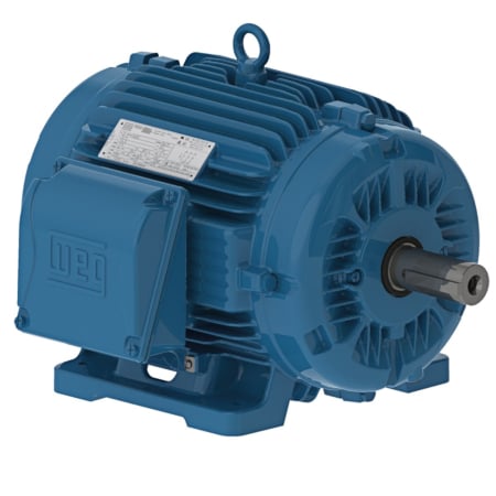
Figure 1. The nameplate on a general-purpose electric motor. Image used courtesy of WEG
Section 430.7(A) Usual Motor Applications
Mark the motor with the following information:
1. Manufacturer’s name. This mark identifies the firm that makes the motor. Typically, the nameplate includes the firm address.
2. Rated volts and full-load current. Rated voltage is the type (DC or AC) and voltage magnitude on which the motor is designed to operate. There is a tolerance, however.
The NEMA standard tolerates a +/- 10% range for small- and medium-voltage electric motors—with an allowable +/- 5% frequency variation. For example, a 460 V motor, working at 60Hz +/- 5%, may operate from 414 V to 506 V. Voltage variations will impact the full-load current, power factor, efficiency, starting current, and starting torque.
Supplying the motor with any other voltage will cause it to function outside its normal operating parameters and may produce a failure.
When the motor operates at full-load torque and speed at rated voltage and frequency, the power line supplies full-load current.
Multispeed motors must show the full-load current for each speed. Exceptions are shaded-pole and permanent-split capacitor motors where only the current for maximum speed is required.
3. Rated frequency and number of phases. The rated frequency is the one at which the motor operates per design. The frequency, measured in Hertz (Hz), must match the power supply to ensure the motor operates efficiently and reliably.
The standard electrical power frequency in the United States is 60 Hz. In other regions, like Europe, the frequency is 50 Hz. Although the standard electrical power frequency varies worldwide, there are only two options: 60 Hz or 50 Hz.
Regarding the number of phases, the motor categories are single-phase and three-phase. Both types have similarities and differences, and their distinctive operating and performance characteristics make them suitable for particular applications.
4. Rated full-load speed. The rated full-load speed is the operating speed under full-torque conditions when the voltage and frequency are constant at the rated values. It is usually expressed in RPM (Revolutions Per Minute) or S ˉ ¹ (1/Second).
5. Rated temperature rise or the insulation system class and rated ambient temperature. Temperature rise and insulation class involve motor capabilities when operating in specific ambient temperatures.
Temperature rise is the amount by which a motor, operating under rated conditions, is hotter than its surrounding ambient temperature – the difference between the motor’s initial and final temperatures.
The losses in a motor are transformed into heat, which causes the motor temperature to rise above that of the surrounding air. The temperature becomes stationary when the heat generation rate equals the heat dissipation rate.
The generation rate depends on the magnitude of the losses, while the dissipation rate depends on the difference between the temperature of the machine and that of the surrounding air.
Insulating materials lose their mechanical and dielectric strengths at high temperatures. The temperature rise of a motor loaded to its rating or service factor must not exceed the limit for the insulation system.
Smaller induction motors show the insulation class and maximum ambient temperature. Larger motors show the temperature rise above an ambient of 40 °C and may include stator and rotor data.
Table 1 shows the temperature rise for four insulation classes based on an ambient temperature of 40°C and 1,000m altitude. Temperature measured by the resistance method.
Table 1. Temperature rise for integral horsepower single-phase and polyphase induction motors
|
Insulation System Class |
Maximum Temperature Rise |
Maximum Temperature Rise Service Factor = 1.15 |
Maximum Attainable Temperature at the Winding |
|
A |
60°C |
70 °C |
105 °C |
|
B |
80°C |
90 °C |
130 °C |
|
F |
105°C |
115 °C |
155 °C |
|
H |
125°C |
_ |
180 °C |
The maximum attainable temperature at the winding includes an allowance for the “hotspot.” For example, adding the maximum temperature rise for a Class F insulation to the rated ambient temperature gives 105°C + 40°C = 145°C. The maximum attainable temperature at the winding is 155 °C, giving the hotspot a 10°C margin.
Hotspots can damage the insulation at those places due to extreme heating, potentially yielding outages.
6. Time rating. The time rating denotes how long the motor can operate at its rated load and ambient temperature. The NEC establishes two classes of time ratings: continuous and intermittent.
Continuous rating is a service requirement that demands operation with a constant load for an indefinitely long time—long enough to reach temperature equilibrium. This rating is the most common classification, accounting for 90% of motor applications. An example is a pump motor, which may run for hours or days.
Intermittent rating is a service requirement that calls for operation at alternating intervals of load and no load, load and rest, or load, no load, and rest, each of the specified intervals. These motors never reach equilibrium temperature but can cool to ambient temperature between operations. The NEC allows the following intermittent time ratings: 5, 15, 30, or 60 minutes. Examples are cranes, hoists, machine tool motors, and valve actuators, often rated for 15, 30, or 60-minute duty.
7. Rated horsepower if 1/8 hp or more. The rated horsepower is the motor’s mechanical output rating – its capacity to provide the torque needed for the load at the rated speed.
Multispeed motors rated 1/8 hp or more must show the rated hp for each speed. The exceptions are shaded-pole and permanent-split capacitor motors, rated 1/8 hp or more, where the requirement is only for maximum speed.
There are no requirements to mark the hp rating of the arc welder motors.
8. Code letter or locked-rotor amperes if an AC motor rated ½ hp or more. All AC motors rated ½ hp or more, except polyphase wound-rotor machines, show a code letter. The code letter corresponds to a range of locked-rotor kVA per horsepower at rated frequency and voltage and entails letters from A to V (except I, O, and Q).
NEC Table 430.7(B) lists such code letters and corresponding kVA per horsepower with a locked rotor. The 1940 NEC included the code letters for the first time.
Table 2 includes some of the letters shown in Table 430.7(B).
Table 2. Connecting code letters to locked-rotor kVA/hp
|
Code Letter |
kVA/hp with Locked Rotor |
|
A |
0 – 3.14 |
|
B |
3.15 – 3.54 |
|
C |
3.55 – 3.99 |
|
D |
4.0 – 4.49 |
|
V |
22.4 and up |
These figures permit estimating the full-voltage starting current and the motor’s subtransient reactance (Xd´´).
Example: Estimate (a) the full-voltage starting current and (b) the subtransient reactance of a 3-phase, 21,000 hp, 6,600 V, synchronous motor with code letter B and 1,404 A full-load current.
Answer:
a. From Table 2, the locked-rotor kVA/hp ranges from 3.15 to 3.54. The locked-rotor or full-voltage-starting current varies from:
3.15 kVA/hp x 21,000 hp = 66,150 kVA
Power per phase = 66,150 kVA/3 = 22,050 kVA
Phase voltage = 6,600 V/√3 = 3,810 V
Locked-rotor or full-voltage-starting current = 22,050 kVA/3,810 V = 5.79 kA
to
3.54 kVA/hp x 21,000 hp = 74,370 kVA
Power per phase = 74,370 kVA/3 = 24,780 kVA
Phase voltage = 6,600 V/√3 = 3,810 V
Locked-rotor or full-voltage-starting current = 24,780 kVA/3,810 V = 6.50 kA
b. The approximate subtransient reactance per unit on the motor base is the full-load current divided by the locked-rotor current. This value varies from
1,404 A/5,790 A = 0.242 per unit to 1,404 A/6,500 A = 0.216 per unit
on a base of √3 x V x I = √3 x 6,600 V x 1,404 A = 16,049 kVA
Base MVA in one phase = 16.049/3 = 5.35
Base impedance = (3.81 kV) ² /5.35 MVA = 2.71 Ω
The approximate subtransient reactance in ohm varies from 0.242 x 2.71 = 0.656 Ω to 0.216 x 2.71 = 0.585 Ω.
9. Design letter for design A, B, C, or D motors. The National Electrical Manufacturers Association (NEMA) labels the design letters. The letters A, B, C, and D express the motor torque/speed characteristics, percent slip, and full-voltage, rated-frequency starting current. Most motors are designed A and B.
Design B motors—with normal torque and low starting current—have many applications, including blowers, fans, pumps, and machine tools.
Design C motors—with high torque and low starting current—are used with hard-to-start loads, such as conveyors, reciprocating pumps, and compressors.
Design D motors—with high slip—are used for high-inertia loads, such as shears, punch presses, other flywheel loads, and mechanically coupled conveyor drives.
Design A motors—with normal torque and starting current—are similar to design B but have higher starting current and maximum torque.
Figure 2 shows the speed-torque characteristics for NEMA-standard squirrel-cage induction motor designs.
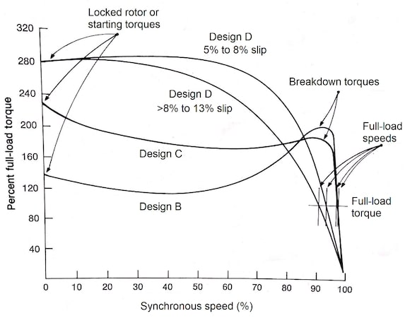
Figure 2. Speed-torque characteristics for squirrel-cage induction motors. Image used courtesy of Lorenzo Mari
10. Secondary volts and full-load current if a wound-rotor induction motor. In addition to other items, wound-rotor induction motors include secondary voltage and current. These values are essential to calculate the rating of the resistors and control equipment employed with the motor to attain the required performance.
The secondary voltage is the open-circuit voltage at a standstill, measured across the slip rings (when using slip-rings and brushes) with rated voltage in the primary.
The secondary current is related to the rated horsepower using:
I = (hp x 746)/(√3xVxD) where D is a constant roughly = 0.96.
This type of motor offers variable speed with a low starting current and is employed on conveyors and other high-inertia loads and applications requiring low starting currents.
11. Field current and voltage for DC excited synchronous motors. Synchronous motors necessitate a source of direct current for their field winding. Rating information for synchronous motors includes the nominal field excitation volts and the full-load excitation current at the rated temperature.
The motor field current is usually set at the DC excitation amperes marked on the motor nameplate at all loads. This practice maintains the motor’s full pull-out torque and gives the maximum kVAr for power factor correction.
12. Winding. The classification of direct current motors adheres to the field winding connection employed. The NEC identifies four types of connections:
- Series
- Straight shunt
- Stabilized shunt
- Compound
The series-wound motor has the field winding and armature connected in series, allowing the entire current to flow through the field winding (Figure 3).
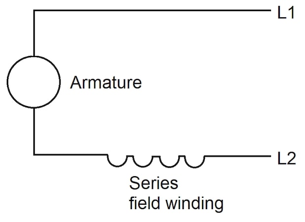
Figure 3. Series-wound DC motor. Image used courtesy of Lorenzo Mari
The shunt-wound motor has the field winding and the armature connected in shunt (parallel). In this arrangement, the field current is a small portion of the total current (Figure 4).
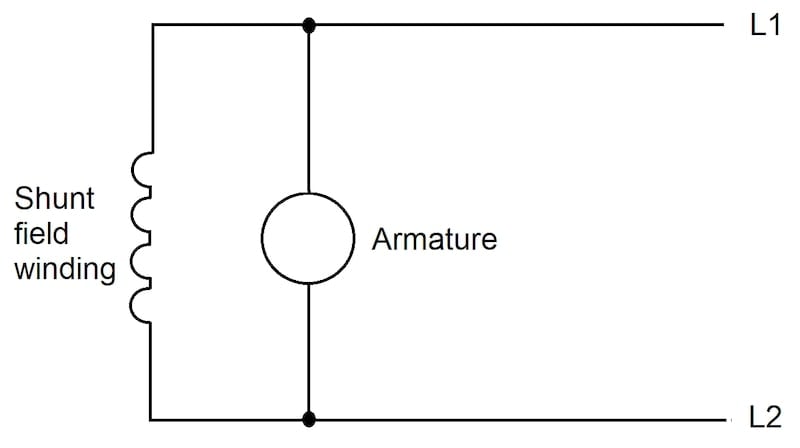
Figure 4. Shunt-wound DC motor. Image used courtesy of Lorenzo Mari
A straight-shunt-wound motor has only one shunt field. The field circuit may be connected either in shunt with the armature circuit or to an independent excitation voltage source. Only the shunt field winding supplies field excitation.
A stabilized shunt-wound motor has the shunt field circuit connected either in shunt with the armature circuit or to an independent excitation voltage source. It also has a light series winding to avoid a rise in speed or to attain a slight speed reduction when the load increases.
The compound-wound motor combines the series-wound and the shunt-wound field winding connections (Figure 5).
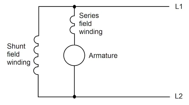
Figure 5. Compound-wound DC motor. Image used courtesy of Lorenzo Mari
Fractional horsepower DC motors with a diameter of 175 mm or less do not need to be marked.
13. Motors containing thermal protectors complying with sections 430.32(A)(2) “Separate Overload Device” or (B)(2) “Thermal Protector or Electronically Protected” must be marked “thermally protected.” Thermal protectors protect against a high winding temperature that could cause the winding insulation to break down and fail.
Motors rated 100 W or less and complying with Section 430.32(B)(2) may use the shortened marking “TP.”
14. Motors complying with Section 430.32(B)(4) “Impedance-Protected“ must be marked “impedance protected.” The impedance protection method prevents burning damage when the motor is blocked so it cannot rotate. The motor winding impedance limits the current to a value that does not exceed the rated temperature rise. This method applies to small motors, like fans.
Motors rated 100 W or less and complying with Section 430.32(B)(4) may use the shortened marking “ZP.”
15. Motors with electrically powered condensation prevention heaters must be marked with the rated voltage, rated power (in watts) and number of phases. Motor heaters warm the windings, counteracting moisture condensation through convection when moist air contacts the cold metal surface. This method helps reduce premature winding failure.
16. Motors electronically protected against overloads, per sections 430.32(A)(2) “Separate Overload Device” and (B)(2) “Thermal Protector or Electronically Protected” must be marked “electronically protected” or “EP.” An electronically protected motor has an integral electronic control that protects against malfunction of the electronic control, overload, and failure to start.
Motor and Multi-Motor Equipment Marking Takeaways
- All electric motors have a nameplate containing essential information for correct installation, operation, and maintenance.
- NEC Section 430.7 establishes the information the motor manufacturers must display on the nameplates, defining the motor´s essential electrical performance.
- The NEC rules cover DC, squirrel cage, wound-rotor, and synchronous motors.
- Manufacturers can include additional information to support installing, operating, and maintaining custom and specific-purpose motors.