Facebook
 Google
 GitHub
 Linkedin
Using DC-DC Converters in Parallel
This article discusses methods in using two DC-DC converters in parallel operation for better reliability and redundancy for devices.
A technique that sets out power supplies in parallel is interesting and feasible which takes advantage in inventory and stocking, product commonality, additional output current, and N+1 redundancy. But, this technique is possible by recognizing the potential paralleling topologies and how to maintain the closed-loop supply regulation across multiple supplies.
The apparent and easiest method of putting supplies in parallel is to bind their outputs together. Normally, this method won’t work due to the individual supply’s output voltage regulation, which makes it trying to maintain the regulation with changes in load, as well as regulating against the closed loops of the other supplies.
This also applies to supplies which include their own traditional internal error amplifier and reference, where parametric differences from supply to supply will always cause one supply to carry all the load current, while all the remaining supplies will carry no load, with resultant overstressing and potential collapse of the entire supply rail.
One way in which this direct-connect topology can work well is if one supply is set to constant-voltage (CV) mode and the others are set to constant-current (CC) mode, but at slightly higher output voltage – bearing in mind that not all supplies allow a choice of output mode. The supplies, which are set to the higher, output voltage will provide a constant-current output, and each of their output voltages will drop until it equals the output of the CV supply. The load must draw enough current to ensure that the supplies, which are in CC mode, must stay in that mode.
The direct-connect approach is viable if the supply is specifically designed to support that topology, or if there is a single control-loop error amplifier, which feeds the error signal back to all of, the other supplies so that they share the load. However, the latter method also requires a “share bus” for the control signals from the master to the slaves.
Another approach adds small ballast resistors in series with each supply’s output to equalize the distribution of the load current among the supplies in the array (Figure 1). The ballast resistors create some loss of load regulation and also dissipate heat, which degrades system efficiency.
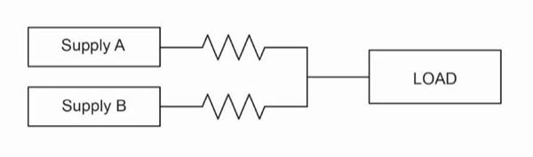
Figure 1: One sharing approach is to use relatively low-value ballast resistors on each supply’s output, but this has issues due to resistor-related dissipation and overall efficiency
Use of Diode OR-ing
A seemingly “simple” solution to this direct-connect dilemma is to use a diode between each supply and the common tie point of all the supplies: a technique commonly referred to as “diode OR-ing” (Figure 2). OR-ing diodes are very effective at preventing a supply from sinking current away from the shared output but are generally insufficient to address sharing errors among supplies with independent error amplifiers.
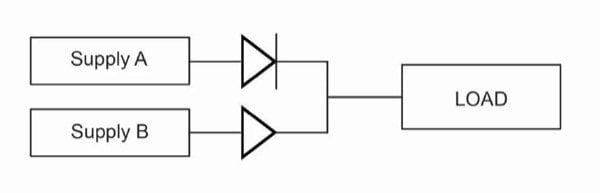
Figure 2: In principle, multiple DC-supply outputs can be combined by using diodes to isolate one supply from the other, but this configuration has many performance issues related to balancing and current sharing
Diode OR-ing is generally required for supplies acting independently whose outputs can both sink and source current (two-quadrant operation). The effect of directly paralleling such supplies without OR-ing diodes is far worse than it is for single-quadrant supplies, and is likely to lead to the immediate overload of one or more of the supplies.
In addition, if the diodes have a negative temperature coefficient for their conduction threshold, they will actually promote current “hogging” in the array. One way to minimize the problem is to use a method of rectification with a positive temperature coefficient.
Under some circumstances – for example, if one of the supplies suffers a shorted output FET or capacitor, OR-ing can still offer reliability improvements because the OR-ing diodes will quickly decouple the short from the output bus, improving reliability and system robustness.
Control Strategy for Excellent Output-Voltage Regulation
Supplies generally must be designed specifically for parallel operation in order to operate reliably and predictably in an array. For a parallel array of supplies to deliver increased levels of usable current to a load, some type of control-loop strategy that factors in array use is needed. A popular control strategy is to group the supplies together with a common control signal input controlled by a single error amplifier whose single feedback signal is then distributed to all the supplies in the system.
This strategy offers excellent output-voltage regulation and reduced sharing errors, but the use of a single error amplifier and a single wired control bus represents a single point of failure, which may present a problem for some types of high-reliability systems. In addition, parametric errors on modulator gain can be difficult to control.
For a single control-loop approach, sharing errors are minimized if the supplies feature tight tolerance on their control-node inputs. If the sharing errors are large, then either the power rating of the array must be reduced to avoid overloading of any single supply in the array due to sharing imbalances, or specific countermeasures need to be used.
Techniques for sharing errors which result from part-to-part variations of the control node include a production-based adjustment to calibrate out errors, or adding a current-control loop local to each supply inside the array. Sensing current for these local loops typically involves adding a shunt resistor to the supply.
A further problem for isolated power supplies that have their control nodes referred to the primary side of the DC-DC converter results from transmitting the output of the error amplifier across the primary-to-secondary isolation boundary. Isolation techniques often add cost, take valuable board real-estate, and can have adverse effects on reliability.
An alternative control-loop strategy, which permits separate supplies to be arranged in a parallel array, uses a load line to emulate the path resistance of the ballast resistor method. By implementing what is called the “droop share” method of load sharing, each supply has a separate reference and integrating error amplifier, but the reference is deliberately and linearly reduced by a nominal amount as the load current of the supply increases.
Paralleling supplies may have negative consequences on transient response and load regulation, particularly for droop-share arrays. However, an external control loop can be used around the droop-share array to effectively cancel out the negative-regulation term. The resulting static-regulation error is identical to that in the traditional error-amplifier case since the external loop is itself an error integrator.
Power-Supply Design
Power-supply vendors can take steps to ease the paralleling challenge. For example, Vicor’s DCM DC-DC converters in “Converter housed in Package” (ChiP) packaging feature a built-in negative-slope load line; thus, as the load increases, the DCM’s internal regulator reduces the output voltage slightly. This effectively acts as the small ballast resistor approach but without any actual resistors (Figure 3) and with a few additional key differences: notably a lack of wasted heat in physical resistors and enhanced dynamic response due to the lack of high-frequency parasitic effects. As a result, any instantaneous change in voltage across the resistor results in an immediate corresponding change in current.
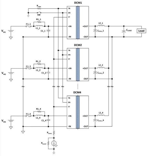
Figure 3: Vicor’s DCM devices in ChiP packaging are designed to be paralleled by simply connecting their outputs together; no diodes, ballast resistors, or other load-balancing components are needed
In the DCM converters, the load line is implemented through a discrete time modulation of the digital/ analog converter that creates the reference for the error amplifier. As a result, the resistor that the DCM load line emulates is one that acts as if it has a significant capacitor in parallel with it.
This load-line output characteristic permits multiple DCM outputs to be placed directly in parallel, with each having its own error-amplifier control-loop still active. The distribution of the load current over the DCMs in the array is ideally equal, so that parallel DCMs thus behave like a single DCM but with a higher output current (Figure 4).
If one supply is loaded more than the others, its temperature will rise relative to the others, which in turn will cause its output voltage to decrease. Since the output voltages of the other parallel DCMs match that of the loaded DCM, their outputs follow their load lines, increasing their share of the load current and bringing the circuit back to equilibrium.
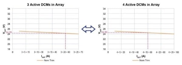
Figure 4: With Vicor DCM converters, units connected in parallel perform as a single converter; also, as the load-line shows, if the array is sized as N+1 redundant relative to the maximum load, the array continues to function despite the failure of any single converter
Similar considerations apply to power-supply ICs that are intended for much smaller loads. For example, the LT3083, a 3 A low-dropout (LDO) linear regulator from Linear Technology Corporation, supports parallel operation using a 10 milliohm ballast resistor between each supply and the common output rail.
About the Author
Arthur Russell serves as a Product Line and Applications Engineer with the Vicor Power Components division of Vicor Corporation in Andover, Massachusetts. He supports customer design-in activities for new product offerings, creates requirements for roadmap products and performs typical applications engineering activities such as datasheet generation, system-level validation and design of reference systems to showcase new products.
This article originally appeared in the Bodo’s Power Systems magazine.