 Facebook
 Google
 GitHub
 Linkedin
What Is Meant By Electrical Resistance?
Voltage, Current, Energy, and Power
Different materials react to voltage in different ways. If a material allows a significant amount of current to flow even when the applied voltage is small, we call it a conductor. If very little current flows even when the applied voltage is large, the material is an insulator.
The property that determines how much current will flow in response to a given voltage is called resistance (denoted by R). A piece of wire made from a highly conductive metal (such as copper) will have low resistance, and a piece of the rubber insulation that surrounds the wire will have high resistance.
The Resistor
One of the most common electronic components is the resistor. As the name implies, these devices resist the flow of electric current. Resistors play a very important role in electrical circuits—not because they simply resist current, but because they resist it in a precise and controllable way.
The unit that we use to specify the resistance of a resistor is the ohm, denoted by the symbol Ω. A resistor with very low resistance—for example, less than 1 Ω—could be considered a conductor. If the resistance is in the tens of millions of ohms, the resistor will function like an insulator. Moderate values of resistance, such as 470 Ω or 10,000 Ω, don’t really fit into the conductor category or the insulator category.
Series and Parallel Connections
Circuits often include more than one resistor. If resistors are connected in such a way that the same current flows through them, they are in series. For example:
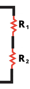
Figure 1. Resistors connected in series.
To calculate the total resistance, also known as the equivalent resistance, of series-connected resistors, you simply add the individual resistance values. In this example, the equivalent resistance is R1 + R2.
When resistors are connected in parallel, they have the same voltage across their two terminals:
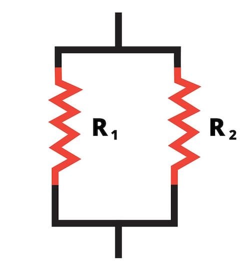
Figure 2. Resistors connected in parallel.
In this case, calculating the equivalent resistance is not so easy. When there are only two resistors, you can use the “product over sum” formula:
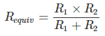
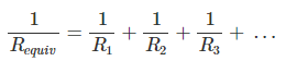
If there are more than two resistors in parallel, you must use the following expression:
Ohm's Law
The following formula expresses the relationship between voltage, current, and resistance:
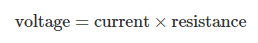
The abbreviated form is:

This is called Ohm’s law. It is the foundation of basic circuit analysis, used constantly by students and professionals alike. The form given above calculates voltage based on current and resistance, but the equation can be rearranged as needed:

or:

If we translate these three equations into words, we will have a good explanation of Ohm’s law:
- If a current I is flowing through a component with a resistance R, the voltage across that component is equal to I multiplied by R.
- If a voltage V is applied to a component with resistance R, the resulting current flow through that component will be V divided by R.
- If a component’s voltage drop is V and a current I is flowing through it, that component’s resistance is V divided by I.
Applying Ohm's Law
Let’s look at a simple example of how Ohm’s law can be used to find an unknown quantity. In this case, we’ll solve for current.
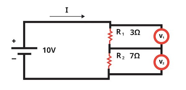
Figure 3. A simple circuit consisting of a battery and two series-connected resistors.
As you can see, the voltage across the pair of resistors is known (it’s the same as the battery voltage) and both resistance values are known. We want to find out how much current is flowing through the resistors.
The first step is to calculate the equivalent resistance.
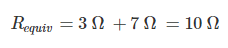
For this portion of the analysis, we can replace the original circuit with this simplified version:
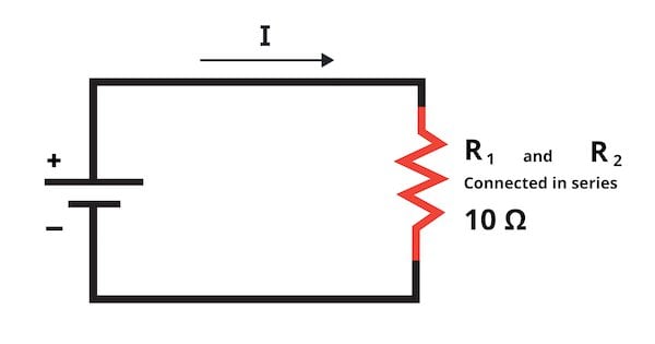
Figure 4. A simplified version of a simple circuit.
Ohm’s law tells us that the current through the series-connected resistors will be:
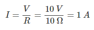
In this circuit there are no other current paths, so if 1 A is flowing through the resistors, 1 A is also the total current supplied by the battery.
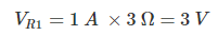
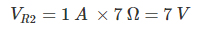
Now let’s calculate the voltage drop across the resistors. We know that voltage is equal to current times resistance, so even though the two resistors have the same current, the voltage drops will be different because the resistances are different.
Power Dissipated by a Resistor
The previous page mentioned the example of a resistor dissipating power (in the form of heat) into the surrounding environment. Ohm’s law enables us to calculate the power dissipation of a resistor if we know
- the voltage across the resistor and the current flowing through the resistor, or
- the voltage across the resistor and its resistance, or
- the current flowing through the resistor and its resistance.
The first of these options is based on the formula for electrical power given in the previous page:
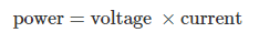
Or in abbreviated form:

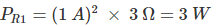
The second two options are the result of combining this formula with Ohm’s law:
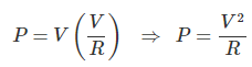
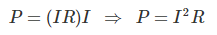
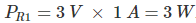
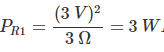
Let’s use the voltage and current values for R1 to verify that all of these formulas produce the same result:
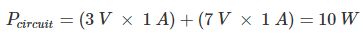
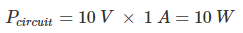
If we want to know the power consumed by the entire circuit, we can add up the power dissipation of the individual components, or we can multiply the voltage of the power source by the current supplied from the power source:
Resistors and Ohm's Law Review
We discussed the resistor, which is one of the most important electronic components, and we looked at three different ways to calculate a resistor’s power dissipation. We also saw how Ohm’s law can help us find an unknown current, voltage, or resistance.
In the next page, we’ll talk about power ratings and how they influence circuit design.
Soo good
Thak u