Facebook
 Google
 GitHub
 Linkedin
Understanding Capacitance and Capacitor Dimensions
A capacitor consists of a layer of insulating material sandwiched between two metal plates. The capacitance can be calculated using the capacitor dimensions and the permittivity of the insulating material, which this article will examine.
The charge quantity stored by a capacitor with a given terminal voltage is its capacitance. The capacitance of a capacitor has a definite relationship to the area of the plates and the thickness of the dielectric.
Refer to Figure 1(a) and recall that electrons are attracted to a positive voltage. The presence of the positive voltage on the top plate causes electrons to be attracted (from the negative terminal of the battery providing the voltage) into the (nearby) bottom plate of the capacitor. The electrons cannot pass through the insulating dielectric to the positive top plate. Instead, they get as close to the top plate as possible by accumulating at the surface of the bottom plate close to the dielectric. Similarly, the negative voltage on the bottom plate causes electrons to be driven out of the adjacent top plate. Consequently, a positive charge (i.e., a lack of electrons) is accumulated at the surface of the top plate close to the dielectric.
Now, look at Figure 1(b), which shows a capacitor consisting of two metal plates with a very thick dielectric between them. With such a thick piece of insulating material between the two plates, the voltage on each plate has very little influence on the electrons in the other plate. Consequently, only a relatively small charge can be stored. In Figure 1(c), a capacitor with a very thin dielectric is shown. In this case, the voltage on each plate has a strong influence on the very close adjacent plate. The result is, of course, that a relatively large number of electrons is accumulated on the bottom plate, and an equally large number of electrons is driven out of the top plate, constituting a relatively large charge on the capacitor. This suggests (and it can be experimentally demonstrated) that the amount of charge stored in a capacitor is inversely proportional to the thickness of the dielectric.
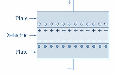
(a) Charges accumulate at the plate surfaces close to the dielectric
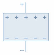
(b) Low charge accumulation on the plates of a capacitor with a thick dielectric
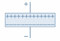
(c) High charge accumulation on a thin dielectric capacitor
Figure 1. A capacitor with a thin dielectric (plates close together) can store more charge than a similar capacitor with a thick dielectric (plates far apart). Image used courtesy of Amna Ahmad
Figure 2 shows two identical capacitors connected in parallel. If each capacitor has a charge of Q coulombs, the total charge stored by the two is 2Q. Paralleling the two similar capacitors means that the plate area has been doubled. So, a capacitor with twice the plate area would also store twice the charge. Now it can be written
\[Capacitance\,a\frac{plate\,area}{distance\,between\,plates}\]
Or
\[C=\frac{A}{d}\]
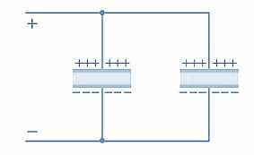
Figure 2. Connecting two capacitors in parallel increases the total plate area and the capacitance. Image used courtesy of Amna Ahmad
Refer to Figure 1, where, for a given applied voltage, a specific number of electrons is attracted into the bottom plate, and the same number of electrons is driven out of the top plate of the capacitor. If the applied voltage is doubled, twice as many electrons are displaced from the positive plate to the negative plate, and the accumulated charge is doubled. The charge on a capacitor is directly proportional to the applied voltage and the capacitance of the capacitor:
\[Q\,a\,CE\]
The farad1(F) is the SI unit of capacitance that contains a charge of 1 coulomb when the difference across its terminals is 1 volt.
A farad is a large unit; consequently, microfarads (mF), nanofarads (nF), and picofarads (pF) are most frequently used for expressing capacitance. The equation for charge becomes
\[Q=CE\,(1)\]
Where C is capacitance in farads and E is the voltage difference between the plates in volts, Q is charge in coulombs.
Permittivity
Electric permittivity is analogous to magnetic permeability. It specifies the ease with which electric flux is permitted to pass through a given dielectric material. Like permeability, permittivity is subdivided into the permittivity of free space (εo) and the relative permittivity (εr), also known as the dielectric constant. Table 1 lists the relative permittivity for various dielectric materials. Note that the permittivity of air is 1.0006, so it is usually taken as 1 (i.e., the same as for vacuum)
Table 1. Dielectric constants for various materials
|
Material |
Typical Dielectric Constant |
|
Vacuum |
1 |
|
Air |
1.0006 |
|
Ceramic (low loss) |
6 to 20 |
|
Ceramic (high loss) |
>1000 |
|
Glass |
5 to 100 |
|
Mica |
3 to 7 |
|
Mylar |
3 |
|
Oxide Film |
5 to 25 |
|
Paper |
4 to 6 |
|
Polystyrene |
2.5 |
|
Teflon |
2 |
The permittivity of free space
\[\epsilon_{o}\frac{1}{36\pi\times10^{9}}\approx8.84\times10^{-12}\]
The dielectric permittivity has a similar relationship to field strength and flux density, as does the magnetic permeability:
\[\epsilon_{o}\epsilon_{r}=\frac{D}{\xi}\,(2)\]
\(\xi\) is the electric field strength in V/m, D is electric flux density in C/m2 and \(\epsilon_{o}\epsilon_{r}\) is a ratio.
It is interesting to note that
\[\frac{1}{\sqrt{[permeability\,of\,free\,space]\times[permittivity\,of\,free\,space]}}=\frac{1}{\sqrt{\mu_{o}\epsilon_{o}}}\]
\[=\frac{1}{\sqrt{4\pi\times10^{-7}\times\frac{1}{36\pi\times10^{9}}}}=3\times10^{8}\]
\[\frac{1}{\sqrt{\mu_{o}\epsilon_{o}}}\{velocity\,of\,light\,and\,other\,electromagnetic\,waves\,in\,meters\,per\,second\]
Capacitance Equation
The following expressions can be used to determine electric flux density D and electric field strength
\[D=\frac{Q}{A}\]
\[\xi=\frac{E}{d}\]
Substituting D and into Equation 2
\[\epsilon_{o}\epsilon_{r}=\frac{Q}{A}\times\frac{d}{E}\]
And substituting Q from equation 1,
\[\epsilon_{o}\epsilon_{r}=\frac{CE}{A}\times\frac{d}{E}=\frac{Cd}{A}\]
Giving
\[C=\frac{\epsilon_{o}\epsilon_{r}A}{d}\,(3)\]
When A is the plate area in m2 and d is the dielectric thickness in meters, C is the capacitance in farads (see Figure 3).
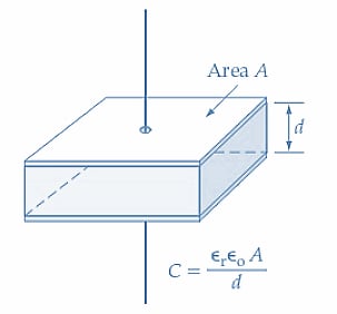
Figure 3. Capacitance can be calculated from the plate area(A), dielectric thickness (d), and the relative permittivity of the dielectric. Image used courtesy of Amna Ahmad
Example 1
Calculate the capacitance of a capacitor with a plate area of 400 cm2 and a dielectric thickness of 0.1 mm: (a) when the dielectric is air, (b) when the dielectric is mica with a relative permittivity of 5. Determine the charge on the capacitor in both cases above when the applied voltage is 25 V.
Solution
(a) Air Dielectric
From equation 3
\[C=\frac{\epsilon_{o}\epsilon_{r}A}{d}=\frac{8.84\times10^{-12}\times400\times10^{-4}m^{2}}{0.1\times10^{-3}m}=3536\,pF\]
(b) Mica Dielectric
From equation 3
\[C=\frac{\epsilon_{o}\epsilon_{r}A}{d}=\frac{5\times8.84\times10^{-12}\times400\times10^{-4}m^{2}}{0.1\times10^{-3}m}=17.68nF\]
Capacitor charge
For Air Dielectric, Equation 1
\[Q=CE=3536\,pF\times25\,V=88.4\times10^{-9}C\]
For Mica Dielectric, Equation 1
\[Q=CE=17.68\,nF\times25V=442\times10^{-9}C\]
Example 2
A 1 µF capacitor is to be constructed from rolled-up sheets of aluminum foil separated by layers of paper 0.1 mm thick (see Figure 4). Calculate the required area for the foil if the relative permittivity of the paper is 6.
Solution
From equation 3
\[A=\frac{Cd}{\epsilon_{o}\epsilon_{r}}=\frac{1\mu F\times0.1\times10^{-3}}{6\times8.84\times10^{-12}}\approx1.89\,m^{2}\]
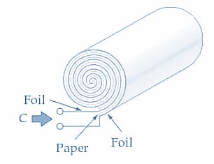
Figure 4. Illustration for Example 2. Image used courtesy of Amna Ahmad
Key Takeaways of Capacitance
Capacitance measures a capacitor's ability to store energy in an electric field between two conductors or "plates." It is defined as the ratio of the electric charge on one plate to the potential difference between the plates and measured in Farad (F).
Capacitor dimensions, such as plate area and plate separation, can affect a capacitor's capacitance. Increasing plate area increases capacitance, and decreasing plate separation decreases capacitance. Factors such as dielectric constant and temperature can also affect capacitance.
Featured image used courtesy of Adobe Stock